Assembly instructions - base/top, 2 base assembly – Mayline RGE User Manual
Page 9
9
Assembly Instructions - Base/Top
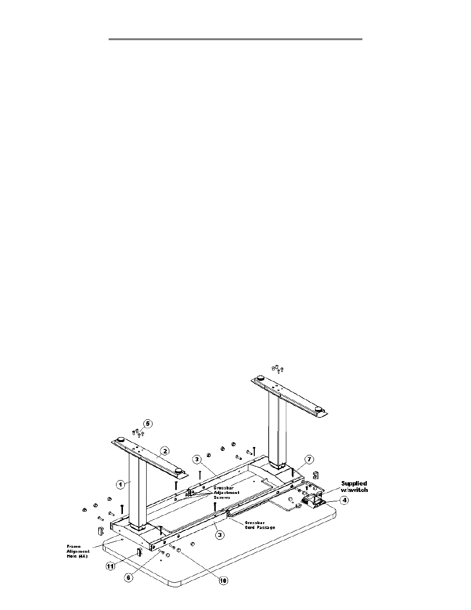
4.2 Base Assembly
1) Place Actuator (1) upside down on clean surface, assemble Foot (2) to bottom of actuator using
16mm screws (5), Qty 4 per foot. CAUTION: Do Not use 25mm screw (5) to attach foot, this will
cause damage to the internal components of the actuator.
2) Loosen crossbar adjustment screws to allow crossbar sections to move freely.
3) Place table top face down on a clean non-abrasive surface. Place both Actuators (1) and Crossbars
(3) in approximate mounting locations.
Note: Use Frame Alignment Holes and outer mounting holes in crossbar as a guide.
4) Attach crossbars to actuator housing using 25mm screws (6), Qty 4 per bar. Cap tube using End Cap
(11) and Hole Plug (10). Refer to Detail 1 on Page 9 for reference.
5) Adjust crossbar to required length by lining up crossbar mounting holes with frame alignment holes
and fasten crossbars to top using 2 1/8” Wood Screws (7).
6) Once base is fully attached, crossbar sections can then be re-tightened.
Caution: Crossbar Cord Passage Hole must be centered in opening. Refer to Detail 2 on page 9.
7) Mount the Handset (4) in desired location wood screws supplied with switch. Refer to Section 4.6
8) Pass motor cords though crossbar and attach to handset. Attach Cable Ties (8) to desired locations
on the underside of the top for cord management.
9) Using one person per side, carefully rotate table onto the base. Plug power cord into handset and
then into wall outlet. See Section 5.3 for setting up handset for first time use.
Note: If optional Mayline Keyboard Platform 19503ATW was ordered, please refer to the Assembly
Instructions provided with that hardware bag.