Ti.224.225-08_pg4, Rohs, Technical information – MAMAC Systems HU-225 User Manual
Page 4: Humidity sensor, Page 4 of 4
Model HU-224/225
Technical Information
TI.224/225-08
HUMIDITY SENSOR
Page 4 of 4
CHECKOUT
DIMENSIONAL DATA
CALIBRATION
1. Verify that the unit is mounted in the correct position.
2. Verify appropriate input signal and supply voltage.
3. Verify appropriate configuration range.
CAUTION: Never connect 120 VAC to these transducers.
Never connect AC voltage to a unit intended for DC supply.
Transducer
Operation
Calibration of HU-224/225-2/3-mA/VDC Humidity
Transducer
Field calibration instructions are provided with the following
precautions and advice:
1. Do not verify comparative RH with a sling Psychrometer.
There are far too many variables which induce errors into
this process. New HU-224/225 RH transducers are already
supplied with calibration.
2. Recalibration must be done in a controlled environment.
Relative humidity must be held stable while making any
adjustment.
3. Verify the output from the device directly with calibrated
instrumentation and verify the RH with calibrated instrumen-
tation, (NOT A CONTROLLER OUTPUT). With the correct
power applied and only a meter connected to the output of
the transducer, ensure that the output is proportional to the
true RH.
4. A)
SINGLE-POINT CALIBRATION:
[NOTE: SELECT EITHER OPTION 1 OR OPTION 2,
BUT NOT BOTH.]
Option 1. Select a controlled humidity environment
between 10 & 40% RH. Insure humidity is
stable and adjust zero trimmer (Z).
Option 2. Select a controlled humidity environment
between 40 & 70% RH. Insure humidity is
stable and adjust span trimmer (S).
B)
TWO-POINT CALIBRATION: Select a controlled
humidity environment between 10 & 40% RH. Insure
humidity is stable and adjust zero trimmer (Z).
Then select a controlled humidity environment between
70 & 75% RH. Insure humidity is stable and then adjust
span trimmer (S).
All units are factory calibrated to meet or exceed published
specifications. If field adjustment is necessary, follow the
instructions below.
MAINTENANCE
Regular maintenance of the total system is recommended to
assure sustained optimum performance.
FIELD REPAIR
None. Replace with a functional unit.
WARRANTY
See Data Sheet for additional information.
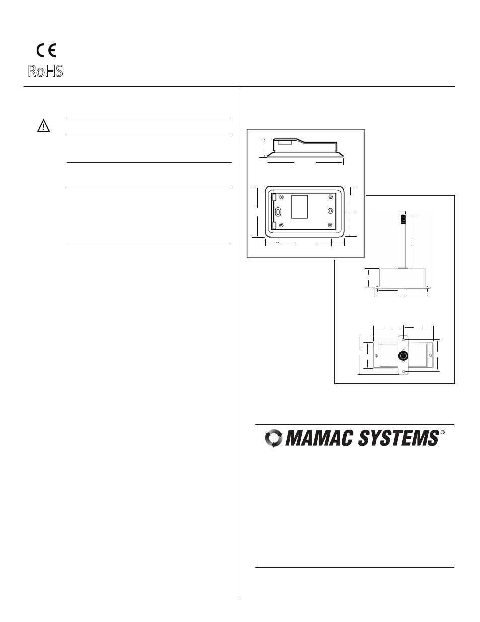
Figure 6 – HU-224/225 Humidity Transducer dimensions shown in inches and
millimeters (mm).
NOTE: The HU-224/225 is a highly accurate device. For
applications requiring a high degree of accuracy, the use of
laboratory-quality meters and gauges are recommended.
TI.224/225-08
RoHS
4.50" (114.31)
1.00"
(25.40)
3.25" (82.55)
.625"
(15.87)
.625"
(15.87)
2.75"
(69.85)
1.375"
(34.92)
1.375"
(34.92)
Wall Mount
HU-225
Duct Mount
HU-224
4.00"
(101.6)
2.63"
(66.8)
3.25"
(82.55)
2.81"
(71.37)
2.81"
(71.37)
5.00"
(127.0)
5.63"
(143.0)
.50"
(12.7)
2.00"
(50.8)
6.00"
(152.4)
For Technical / Application Assistance call your nearest office
8189 Century Boulevard • Minneapolis, MN 55317-8002 • USA
800-843-5116 • 952-556-4900 • Fax 952-556-4997
[email protected] • www.mamacsys.com
EUROPE
4200 Waterside Centre
Solihull Parkway
Birmingham • West Midlands
B37 7YN • United Kingdom
01384-271113 • Fax 01384-271114
AUSTRALIA
4 Armiger Court, Unit 2
Adelaide • S.A.
5088 • Australia
08-8395-4333 • Fax 08-8395-4433
CANADA
675 Cochrane Drive
East Tower • 6th Floor
Toronto • Ontario
L3R 0B8 • Canada
905-474-9215 • Fax 905-474-0876
ASIA
1 Fullerton Road #02-01
One Fullerton
Singapore • 049213
65-31581826 • Fax 65-31581826
MAMAC Systems, Inc., reserves the right to change any specifications
without notice to improve performance, reliability, or function of our products.