Ti.227-02_pg4, Rohs, Model hu-227 – MAMAC Systems HU-227 User Manual
Page 4: Technical information, Outside air humidity & temp sensor, Typical applications (wiring diagrams), Page 4 of 4
Model HU-227
Technical Information
TI.227-02
Page 4 of 4
CHECKOUT
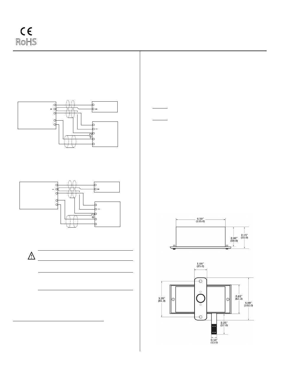
DIMENSIONAL DATA
1. Verify that the unit is mounted in the correct position.
2. Verify appropriate input signal and supply voltage.
3. Verify appropriate configuration range.
CAUTION: Never connect 120 VAC to these transducers.
Never connect AC voltage to a unit intended for DC supply.
Transducer
Operation
MAINTENANCE
Regular maintenance of the total system is recom-
mended to assure sustainted optimum performance.
FIELD REPAIR
None. Replace with a functional unit.
WARRANTY
See Data Sheet for additional information.
Figure 7 - HU-227 Outside Air Humidity & Temp Sensor
dimensions shown in inches and millimeters (mm).
RoHS
TI.227-02
OUTSIDE AIR HUMIDITY & TEMP SENSOR
TYPICAL APPLICATIONS (wiring diagrams)
Neutral
Hot
+
Controller / Meter / Recorder
VDC Output Transducer Only
12-35 VAC Transformer
Figures 5 & 6 illustrate typical wiring diagrams for the HU-227,
0-5/0-10 VDC output humidity transducers.
Figure 5 - Wiring for VDC Output when applied with External AC
Supply
Figure 6 - Wiring for VDC Output when applied with External DC
Power Supply
Signal
+
Common
Supply
O
+
Controller / Meter / Recorder
VDC Output Transducer Only
12-40 VDC Power Supply
Input Signal
+
Common
Shield/Ground
Temp
Input
Input Signal
+
Common
Shield/Ground
Temp
Input
Humidity
Temp
Signal
+
Common
Supply
O
Humidity
Temp
NOTE: The HU-227 is a highly accurate device. For applica-
tions requiring a high degree of accuracy, the use of laboratory-
quality meters and calibration standards are recommended.
Calibration of HU-227 mA/VDC Humidity Transducer
Field calibration instructions are provided with the following precautions
and advice:
1. Do not verify comparative RH with a sling Psychrometer. There are far
too many variables which induce errors into this process. New HU-227
RH transducers are calibrated to NIST standards.
2. Recalibration must be done in a controlled environment. Relative
humidity must be held stable while making any adjustment.
3. Verify the output from the device directly with calibrated instrumenta-
tion and verify the RH with calibrated instrumentation, (NOT A
CONTROLLER OUTPUT). With the correct power applied and only a
meter connected to the output of the transducer, insure that the output
is proportional to the true RH.
4. A)
SINGLE POINT CALIBRATION: [NOTE: SELECT EITHER
OPTION 1
OR OPTION 2, BUT NOT BOTH.]
Option 1: Select a controlled humidity environment between 10 & 40%
RH. Insure humidity is stable and adjust zero trimmer (Z).
Option 2: Select a controlled humidity environment between 40 & 70%
RH. Insure humidity is stable and adjust span trimmer (S).
B)
TWO POINT CALIBRATION: Select a controlled humidity environ-
ment between 10 & 40% RH. Insure humidity is stable and adjust zero
trimmer (Z). Then select a controlled humidity environment between
70 & 75% RH. Insure humidity is stable and then adjust span trimmer (S).
CALIBRATION All units are factory calibrated to meet or exceed
published specifications. If field adjustment is necessary, follow
the instructions below.