Ti.227-02_pg2, Rohs, Model hu-227 – MAMAC Systems HU-227 User Manual
Page 2: Ma output, Technical information, Outside air humidity & temp sensor, Installation
Model HU-227
Technical Information
TI.227-02
OUTSIDE AIR HUMIDITY & TEMP SENSOR
Page 2 of 4
HU-227 humidity transducers are 4-20 mA output units powered
with a 12-40 VDC supply.
The following describes the proper wiring of these humidity and
temp sensors with mA output:
HUMIDITY SENSOR:
1. Remove the terminal block by carefully pulling it off the circuit
board.
2. Locate the [+] and [-] terminal markings on the board.
3. Attach the supply voltage to the [+] lead.
4. Connect the 4-20 mA output ([-] terminal) to the controller’s
input terminal.
5. Ensure that the power supply common is attached to the
common bus of the controller.
6. Re-insert the terminal block to the circuit board and apply
power to the unit.
7. Check for the appropriate output signal using a DVM set on
DC milliamps connected in series with the [-] terminal.
RoHS
Mounting
HU-227 - Refer to Figure 7 for mounting
dimensions.
1. Choose a mounting location so that the unit
is protected from direct sunlight, rain & snow.
2. Mount transducer on a vertical surface with
two #8 self-tapping screws (not provided).
3. Pull wires through knockout & make neces-
sary connections (see wiring diagrams).
4. Replace cover and tighten Philips screws.
Wiring
Use maximum 12 AWG wire for wiring terminals.
Refer to
Figures 2, 3, 5 & 6 for wiring informa-
tion and
Figure 4 for dip switch designations.
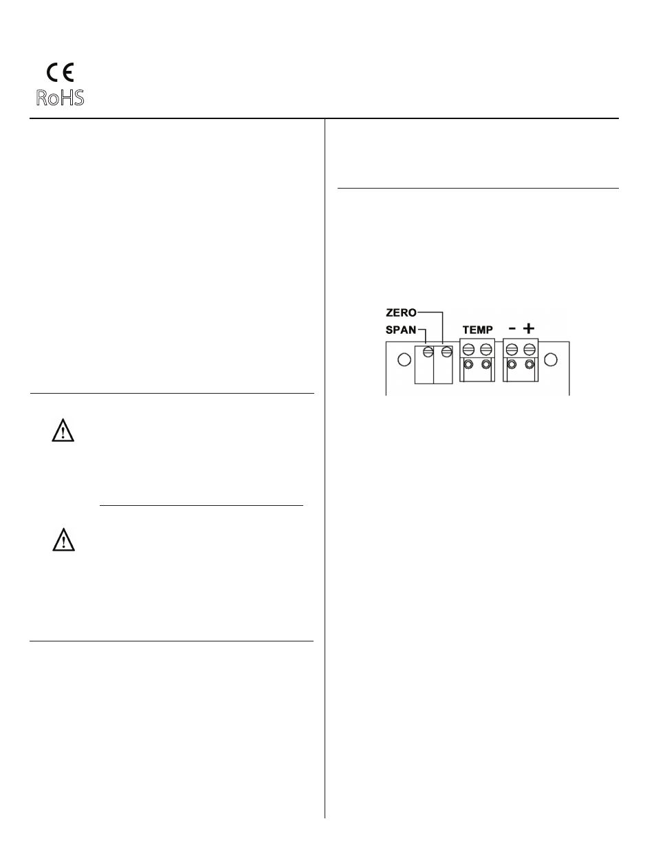
Wiring HU-227 Units with mA Output
Figure 1 - HU-227 Humidity Transducer with mA Output
mA Output
TEMP SENSOR:
1. Remove the terminal block by carefully pulling it off the circuit
board.
2. Use shielded 18-22 AWG wire to connect temp sensor as
shown in
Figures 2 & 3.
INSTALLATION
Inspection
Requirements
Inspect the package for damage. If damaged,
notify the appropriate carrier immediately. If
undamaged, open the package and inspect the
device for obvious damage. Return damaged
products.
• Tools (not provided):
-- Digital Volt-ohm Meter (DVM)
-- Appropriate screwdriver for mounting
screws
-- Appropriate drill and drill bit for mounting
screws
• Appropriate accessories
• Two #8 self-tapping mounting screws (not
provided)
• Training: Installer must be a qualified,
experienced technician
Warning:
• Do not use on oxygen service, in an explosive/
hazardous environment, or with flammable/
combustible media.
• Disconnect power supply before installation to
prevent electrical shock and equipment damage.
• Make all connections in accordance with the job
wiring diagram and in accordance with national and
local electrical codes. Use copper conductors only.
Caution:
• Use electrostatic discharge precautions (e.g., use
of wrist straps) during installation and wiring to
prevent equipment damage.
• Avoid locations where severe shock or vibration,
excessive moisture or corrosive fumes are present.
NEMA Type 4 housings are intended for outdoor
use primarily to provide a degree of protection
against wind-blown dust, rain, and hose-directed
water.
• Do not exceed ratings of the device.