Lowell manufacturing company, Speaker system connections – Lowell PA250 User Manual
Page 6
Instruction Sheet
IS-PA250
Issued: 5-1-14
Lowell Manufacturing Company
100 Integram Drive
Pacific, Missouri 63069 U.S.A.
Call: 800-325-9660
Fax: 636-257-6606
Click: www.lowellmfg.com
6
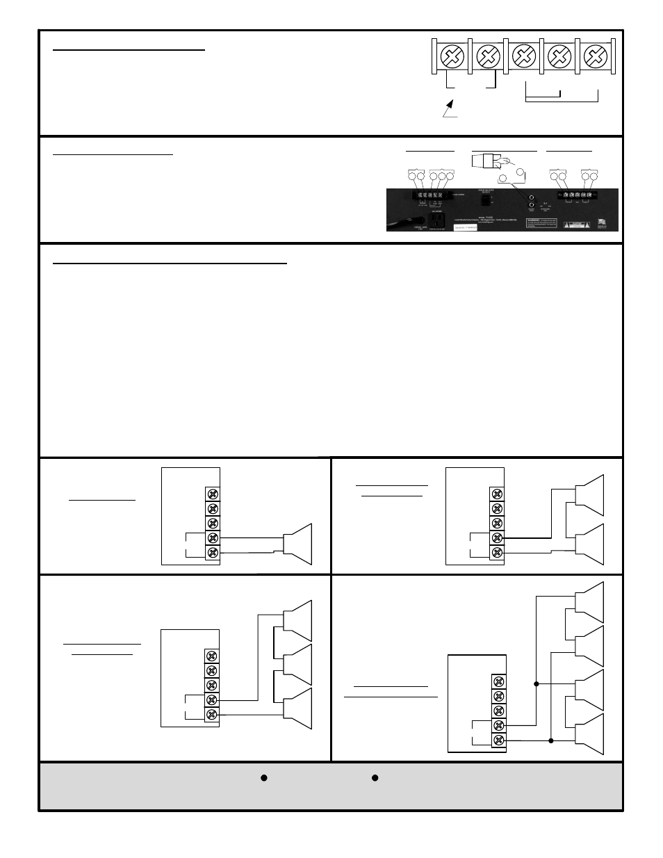
Speaker System Connections
The PA250 includes a speaker output screw terminal strip. Connect an 8
W speaker
line to the 8
W bridged output. For 25V or 70V operation, set the “SPEAKER LINE
OUTPUT” switch to the “IN” position (which inserts the internal 25V/70V output
transformer)
and connect the low side of the speaker line to “C” and the hot side to
the 25V or 70V terminal. Never connect an 8
W speaker system (that has no 25V or
70V matching transformer) to the 25V or 70V output.
Warning: Do not ground either
terminal of the 8
W bridged output.
AMPLIFIER
OUTPUT
8
W Bridged
70V
25V
C
SPEAKER
+
_
8
W
SPEAKER
+
_
8
W
SPEAKER
+
_
8
W
Result: Total amplifier
power is reduced due
to impedance
mismatch. Each
speaker receives 1/3 of
the reduced total
amplifier power.
Three 8
W Speakers
wired in Series
AMPLIFIER
OUTPUT
8
W Bridged
70V
25V
C
SPEAKER
+
_
8
W
SPEAKER
+
_
8
W
SPEAKER
+
_
8
W
SPEAKER
+
_
8
W
Result: Each speaker
receives ¼ of the
total amplifier power.
Four 8
W Speakers
wired in Series/Parallel
SPEAKER
+
_
8
W
AMPLIFIER
OUTPUT
8
W Bridged
70V
25V
C
Result:
One speaker
receives the
total amplifier power.
One 8
W Speaker
AMPLIFIER
OUTPUT
8
W Bridged
70V
25V
C
SPEAKER
+
_
8
W
SPEAKER
+
_
8
W
Result:
Total amplifier power is
reduced due to
impedance mismatch.
Each speaker receives
½ of the reduced
total amplifier power.
Two 8
W Speakers
wired in Series
8 Ohm Series/Parallel Speaker System Wiring
The Lowell PA250 power amplifier includes a bridged direct 8
W output that can drive a basic 8W speaker without the
use of a line matching transformer. The impedance of the speaker load must always be equal to or greater than the
8
W impedance of the amplifier output. For example, it is safe for the amplifier if the 8W output is used to drive an 8W
load or a 16
W load, but it is not safe for the 8W output to drive a 2W load. Overloading the amplifier output can
cause distortion and can damage the amplifier and void the manufacturer’s warranty. It is also important to pay
attention to the power rating of the speakers used. If an 8
W speaker is fed from the 8W output of an amplifier and
the amplifier is turned all the way up, the speaker will receive the maximum power output of the amplifier. A
speaker must be chosen with sufficient power handling capacity for the amplifier used. For example, if an 8
W
speaker can handle 150 watts and it will be fed from the 8
W output of the amplifier, an amplifier with a power output
of 150 watts or less should be chosen so that if the amplifier is turned all the way up, the speaker will be able to
handle the amplifier’s full power output. All of the Series/Parallel configurations shown below will result in load
impedances that will be safe for the amplifier when connected as shown. Depending on the size of the amplifier
used, verify that the maximum amplifier power when divided between the speakers, will not exceed the power rating
of the speaker chosen.
Speaker Signal Polarity
In a paging amplifier, making sure that a positive going input signal
results in a positive going speaker output signal, is often not critical.
If, however, multiple amplifiers feed speakers covering the same
area, observing correct polarity can be important so all speakers are
in phase with each other. The picture to the right shows how inputs
should be wired to result in no polarity change in the PA250.
Speaker Outputs
Direct
Out
25V/70V
Out
Balanced Inputs
RCA Phono Plug Input
8
W
BRIDGED
DO NOT GND
25V(+)
2.5
W
70V(+)
20
W
C( )
+
_
_
+
_
+
_
+
_
+
_
+
+
_
+
_
Sleeve
_
+
Pin
TEL PAGE
Input
_
+
600
W
Input
_
+