Lowell manufacturing company – Lowell PA250 User Manual
Page 5
Instruction Sheet
IS-PA250
Issued: 5-1-14
Lowell Manufacturing Company
100 Integram Drive
Pacific, Missouri 63069 U.S.A.
Call: 800-325-9660
Fax: 636-257-6606
Click: www.lowellmfg.com
5
POWER WIRING
The PA250 includes a power cord with a standard 15A 120VAC 3-pronged grounded plug. A push-to-reset circuit
breaker for the amplifier is provided on the front panel. An unswitched 120VAC (2A max.) convenience outlet is
provided on the rear panel. Warning: THIS UNIT MUST BE EARTH GROUNDED.
PASSIVE CONVECTION COOLING AND VENTILATION
This unit is cooled via passive convection and therefore designed for continuous operation. Excessive heat due to
poor ventilation can shorten the lifespan of electronic equipment and could void the manufacturer’s warranty. Do
not block the amplifier’s vent slots located on the top and bottom of the chassis.
MOUNTING THE AMPLIFIER
The PA250 may be placed on a wooden or metal wall-mount shelf. Do not remove the rubber feet from the bottom
of the amplifier chassis. When the amplifier is placed on a countertop or is shelf-mounted, the rubber feet maintain
the proper spacing under the amplifier for passive convection cooling. Do not place anything on top of the amplifier
where the vents on the top of the chassis would be blocked. Rack mount ears are built into the front panel of the
PA250. If the amplifier will be rack mounted, we recommend that you provide a minimum of 1.75
” of open space
above and below the unit to assure proper ventilation. Provide ventilation fans in the equipment cabinet if that is
required to maintain an amplifier operating temperature of no higher than 92
o
F. To mount the amplifier in a Lowell
equipment cabinet, use standard 10-32 Phillips-head machine screws (like the Lowell model RS or RSP rack
screws) with integral plastic washers to protect the finish of the front panel of the amplifier. The PA250 is very
heavy, so we recommend that you provide rear support for the amplifier when rack mounting it to remove some of
the load from the built-in rack mount ears.
LINE LEVEL “AUX” INPUT CONNECTIONS
The amplifier includes a mono high-impedance unbalanced auxiliary input which may be used for connecting signal
sources such as an AMFM tuner, CD player, Cassette deck, or an unbalanced feed from an equalizer or mixer/
preamplifier. Two (2) parallel RCA-phono connectors are provided for the aux input so stereo input cables can be
connected to this mono input. Mono inputs need only use one or the other of the RCA-phono connectors.
600
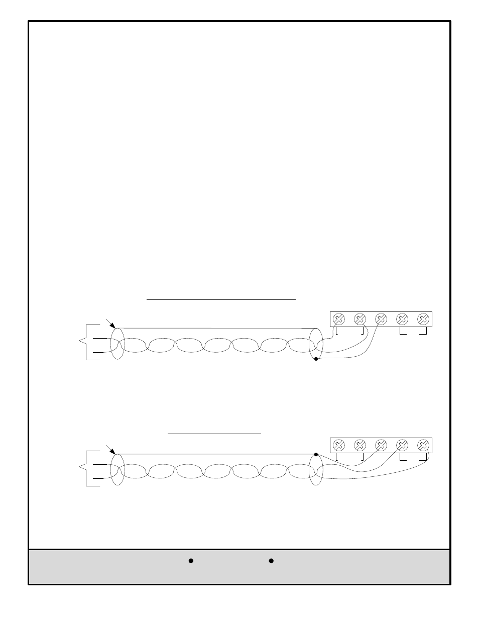
W CHANNEL INPUT WIRING
From an
External
Device
Balanced
Line-level
600
W
Output
600
W Stranded Twisted-Pair Wiring
Shielded wiring from an external device feeding the 600
W
balanced line level would typically be required as shown below.
BUTT SHIELD
(No connection)
DRAIN
SHIELD
The amplifier includes a 600
W line level input channel. This input accepts a low impedance balanced 600W line
level signal that would typically be fed from an equalizer, from another system, or from some other outboard device.
Note: The MIC/TEL Input and the 600
W Line Level Input are both 600W balanced line level inputs, but the MIC/TEL
Input is a “Hotter” input requiring less input signal to drive the amplifier to full power. If distortion results from
feeding the MIC/TEL input with a high level signal, use the 600
W Line Level Input instead.
600
W INPUT CHANNEL
TEL-PAGE
GND
600
W
+
+
_
_
TELEPHONE TEL-PAGE CHANNEL INPUT WIRING
From the
Telephone
System
Page-Port
Output
600
W Twisted-Pair Wiring
Shielded wiring from the telephone system is typically not required, but if
shielded wiring is used, drain the shield at the telephone input and butt
the shield (no connection) at the telephone system page port output.
BUTT SHIELD
(No connection)
DRAIN
SHIELD
TEL-PAGE INPUT CHANNEL
The amplifier includes a telephone input at the TEL-PAGE channel. This input accepts a low impedance balanced
600
W line level input that would typically be available as a page port output from a telephone system. Note: The
MIC/TEL Input and the 600
W Line Level Input are both 600W balanced line level inputs, but the MIC/TEL Input is a
“Hotter” input requiring less input signal to drive the amplifier to full power. If distortion results from feeding the MIC/
TEL input with a high level signal, use the 600
W Line Level Input instead.
TEL-PAGE
GND
600
W
+
+
_
_