Figure 8: six wire load cell wiring schematic – Loadstar Sensors DI-1000U Digital Load Cell Interface Manual User Manual
Page 11
DI-1000
Di1000 User Guide
Page: 11 / 25
P/N : 033-01591 Rev. 6
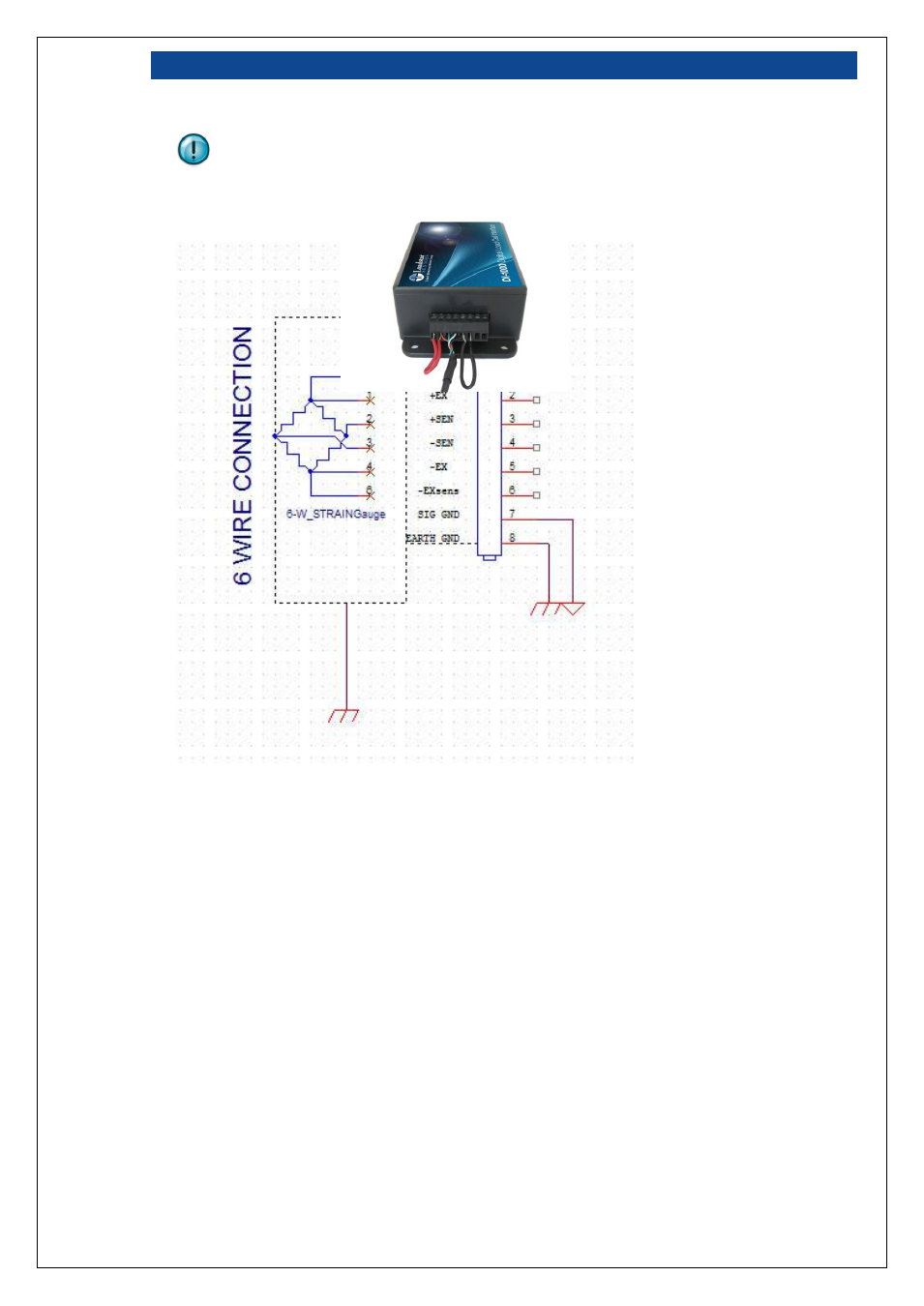
Note that, as shown in the following picture, for a 4-wire load cell, you will need to add an
external jumper between pins 1 and 2 (+EXsens and +EX) as well as between pins 5 and 6 (-
EXsens and
–EX).
Figure 8: Six Wire Load cell Wiring Schematic
We’ve included a handy reference chart below that you can use to help determine how to correctly
wire your load cell to the DI-1000 wiring connector.