4 mounting, 1 mounting gearboxes with solid shafts, Mounting – Lenze g500-H helical gearbox User Manual
Page 15: Mounting gearboxes with solid shafts, Mechanical installation, Stop, Mounting mounting gearboxes with solid shafts, En 15
Mechanical installation
Mounting
Mounting gearboxes with solid shafts
EN
15
Lenze ¯ MA 12.0012 ¯ 1.0
4.4
Mounting
4.4.1
Mounting gearboxes with solid shafts
¯
Draw the transmission elements onto the output shaft only by using the
centering thread.
(
Stop!
Shocks and blows to the shafts damage the roller bearings.
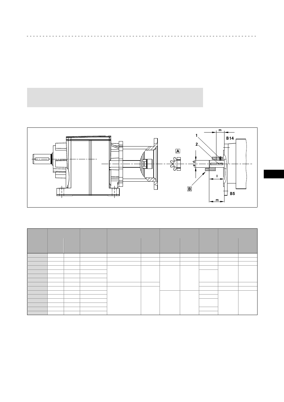
4.4.2
Attachment of motors to gearboxes with bearing housing (input design N)
g500−H_000.iso
Fig. 2
Input side design N
0
Spider / gear rim
1
Locking screw
1
Coupling hub
2
Keyway
Drive size
Motor shaft
Assembly
dimension
Standard hub
Locking screw
Clamping hub
Key
1)
Clamping ring hub
D
[ mm ]
max. l
[ mm ]
M
[ mm ]
Thread
[ mm ]
Tightenin
g torque
[ Nm ]
Thread
[ mm ]
Tightenin
g torque
[ Nm ]
DIN
6885/1
[ mm ]
Thread
[ mm ]
Tightenin
g torque
[ Nm ]
1A
11
23
23
M4
1.5
M3
1.34
*
M3
1.34
1B
14
40
25
M5
2.0
M6
10.5
B5 x 5 x 16
M4
2.9
2B
11
23
23
M4
1.5
M3
1.34
*
M3
1.34
1C
19
40
25
M5
2.0
M6
10.5
B6 x 6 x 16
M4
2.9
2C
14
40
25
B5 x 5 x 16
3C
14
40
25
4C
14
40
25
6C
11
40
25
−−−
−−−
*
−−−
−−−
7C
19
40
25
M5
2.0
B6 x 6 x 16
M4
2.9
1D
24
60
30
M6
10.5
B8 x 7 x 18
M5
6
2D
19
60
30
B6 x 6 x 18
1E
28
60
30
B8 x 7 x 18
2E
24
60
30
3E
19
60
30
B6 x 6 x 18
4E
24
50
50
*
Tab. 3
Attachment of motors to gearboxes with mounting flange
* Use original key for the motor
1)
Key for standard hub and clamping hub