Centre winder with internal diameter calculation, Application examples, 7 centre winder with internal diameter calculation – Lenze EVF9383 User Manual
Page 184
Application examples
Centre winder with internal diameter calculation
3−14
l
EDSVF9383V−EXT EN 2.0
3.7
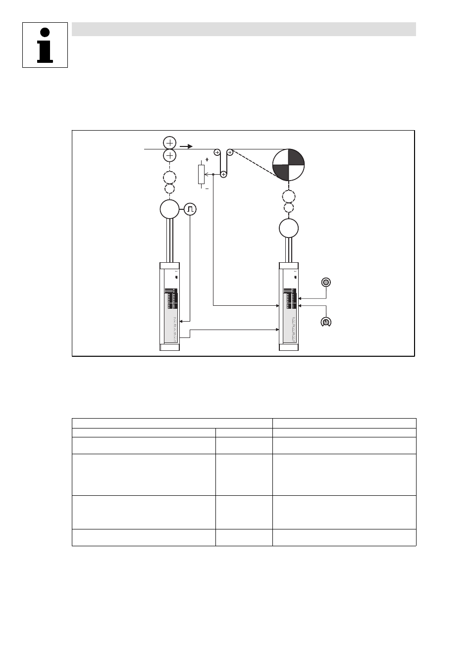
Centre winder with internal diameter calculation
This application is based on the basic configuration C0005 = 9000.
M
M
Q
R
S
T
U
W
X
V
Y
Fig. 3−9
Basic structure of a dancer position control with internal diameter detection
Line speed
Dancer
Winder
Material guide for CW rotation of the winder
Material guide for CCW rotation of the winder
Preset diameter
Actual dancer position
Digital frequency proportional to the line speed
Initial diameter
Input and output assignment
Winding drive
Digital frequency input
X9
·
Line speed
Analog input
X6/1,2
·
Actual dancer position
X6/3,4
·
Initial diameter
Digital inputs
X5/28
·
Controller enable
X5/E1, X5/E2
·
Direction of rotation/quick stop
X5/E3
·
Loading the actual value
X5/E4
·
Accepting the initial diameter
X5/E5
·
TRIP reset
Digital outputs
X5/A1
·
Error (TRIP)
X5/A2
·
Actual dancer position = setpoint
X5/A3
·
Ready for operation (RDY)
X5/A4
·
D
min
/D
max
reached
Analog outputs
X6/62
·
Actual speed
X6/63
·
Motor current