Diameter detection with a distance sensor, Application examples, 6 diameter detection with a distance sensor – Lenze EVF9383 User Manual
Page 182
Application examples
Diameter detection with a distance sensor
3−12
l
EDSVF9383V−EXT EN 2.0
3.6
Diameter detection with a distance sensor
This application is based on the basic configuration C0005 = 8000.
M
M
Q
R
S
V
T
U
W
X
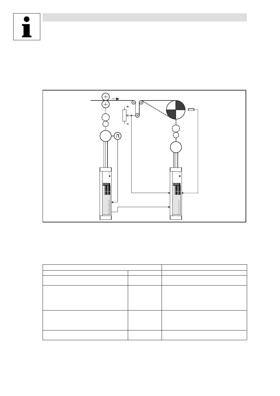
Fig. 3−7
Basic structure of a dancer position control with external diameter detection via a distance sensor
Line speed (material speed)
Dancer
Winder
Material guide for CW rotation of the winder
Material guide for CCW rotation of the winder
Distance sensor (detects the distance to the winding surface)
Actual dancer position
Digital frequency of material speed
Input and output assignment
Winding drive
Digital frequency input
X9
·
Line speed (material speed)
Analog input
X6/1,2
·
Actual dancer position
X6/3,4
·
Signal from distance sensor
Digital inputs
X5/28
·
Controller enable
X5/E1, X5/E2
·
Direction of rotation/quick stop
X5/E3
·
Loading the actual value
X5/E4
·
Reset of dancer position controller
X5/E5
·
TRIP reset
Digital outputs
X5/A1
·
Error (TRIP)
X5/A2
·
Actual dancer position = setpoint
X5/A3
·
Ready for operation (RDY)
X5/A4
·
D
min
/D
max
reached
Analog outputs
X6/62
·
Actual speed
X6/63
·
Motor current
The analog input X6/3,4 (AIN2) is assigned with the signal of the diameter detection. If a distance
sensor is used to detect the reel diameter, gain and offset of the FB AIN2 can be selected in a way
that the diameter signal will be directly generated from the sensor signal.