5] el 5] 5] 5, Lanze – Lenze 490 Series Speed controllers tor DC motors User Manual
Page 16
page: 13
quick stop,
see chapter 8
output armature current signal
The output terminal ~
supplies a signal proportional to
the armature current.
(U
31)
=
5V corresponds approxi—
mately to the nominal current of the controller and can
be used for the direot current display with a measuring
instrument.
The maximum bad
of terminal ~
is
bOmA.
3
GND
Speed
controller
input
Terminal ~
leads to the summation point of the
speed
controller via Ri
50 k[2.
The permissible
input voltage
range is between +10V and -10V.
When switching the
controller inhibit the input is
switched to
zero.
In
this oase Ri ~ 25 k[2.
For positive set value or positive
master voltage and negative actual value a positive
armature voltage is applied at terminal A.
GND, controller reference point
input,
current control,
Ri ~ 10 kfi
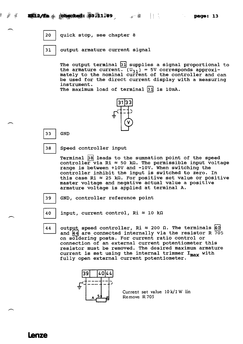
output speed controller,
Ri ~ 200 fl.
The terminals ~
and
are connected internally via the resistor R 705
on soldering posts.
For current ratio
control or
connection of an external current potentiometer this
resistor must be removed.
The desired maximum armature
current is set using the internal trimmer 1
with
fully
open external current potentiometer.
39
1.
durrerit set value 10 k/1 W Im
Remove R705
5]
El
5]
5]
5]
Lanze