Lanze – Lenze 490 Series Speed controllers tor DC motors User Manual
Page 14
**uJ,.
dir~ct
ccble
from uor~troI voltoqe cn
L11
ef~‘org~nCy
si~ cco.e
T
pa9a:
11
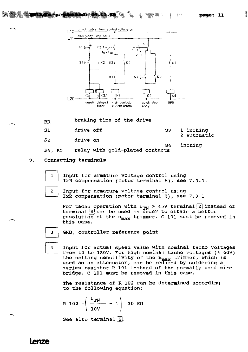
braking time of the drive
drive off
drive on
S3
1 inching
2
automatic
S4
K4,
K5
relay with qold-plated contacts
inching
9.
Connecting
terminals
Input for armature voltaqe control using
IxR compensation
(motor terminal
A), see 7.3.1.
Input for armature voltage
control
using
IxR compensation (motor terminal B),
see 7.3.1
For tacho operation with UTN
> 45V terminal ~
instead of
terminal
~J
can be used in order to obtain a better
resolution
of
the ~
triminer.
C
101 rnust be removed in
this oase.
GND, controller reference point
Input for actual speed value with nominal tacho voltages
from 10 to 180V.
For hiqh nominal tacho voltages
(= 60V)
the setting sensitivity of the
trimmer,
which is
used as an attenuator,
can be r&3uced by soldering a
series resistor R 101 instead of
the nornlally used
wire
bridge.
C 101 must be removed in this oase.
The resistance of R 102 can be determined according
to the following equation:
_
UTN
R102—
—1
3Okf~
)
10V
See also terminals.
on/off deioyed
mein conitoctor
quick stop
RFR
timer
uurrent Cofltrol
reloy
BR
51
S2
El
El
El
El
Lanze