1 parameters, 2 indexer programming example – Lenze E94P v2.0 User Manual
Page 7
7
P940HBK01B
4.1 Parameters
Refer to the PositionServo Programming Manual (PM94P01) for a complete list of accessible variables with
which to program the drive The variables in Table 3 pertain to the use of digital outputs
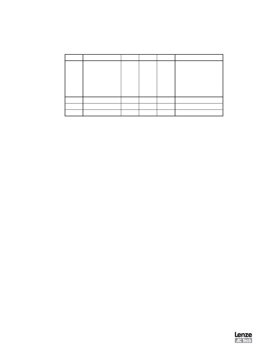
Table 3: Index Variables
Index
Name
Format
EPM
Access
Description
06
VAR_OUT0_FUNCTION
W
Y
R/W
Programmable Output Function
1: Zero Speed
: In Speed Window
3: Current Limit
4: Run Time Fault
5: Ready
6: Brake
7: In Position
07
VAR_OUT1_FUNCTION
W
Y
R/W
Output Function Index
08
VAR_OUT_FUNCTION
W
Y
R/W
Output Function Index
09
VAR_OUT3_FUNCTION
W
Y
R/W
Output Function Index
4.2 Indexer Programming Example
The example below shows how to release and engage the brake using an Indexing program Refer to the
PositionServo Programming Manual (PM94P01) for details
; Demo indexing program for E94ZAHBK2 (Motor Holding Brake Module)
; When enabled, release brake, wait 1 second, run motor.
; When disabled by switch, set speed to zero, wait 1 second,
; then disable output and engage brake.
; For demo, IO -> Digital IO -> Output 2 function should be set to “Not Assigned”
; If Output 2 is set to “Brake”, brake will be immediately engaged when input A3
; enable switch is opened -- and the motor might still be spinning with an
; inertial load.
; A3 input should be to run this program.
; Please Edit SpeedReference constant if you need other speed tuning reference
; Reference is set in RPS.
;*******************************************************************************
Start:
UNITS =1
;set user units to revolutions
VAR_DRIVEMODE = 1
; velocity mode
VAR_REFERENCE = 1
; select Internal reference
IREF = 0
; set speed to zero
VAR_ENABLE_SWITCH_TYPE=0 ; enable switch function set to “Enable only”
VAR_ENABLE_ACCELDECEL =0 ; disable accel/decel for velocity mode
OUT1 = 0
; clear all LED outputs
OUT3 = 0
OUT4 = 0