4operation, 2 j1 - terminal block, Figure : j1 terminal block – Lenze E94P v2.0 User Manual
Page 6
6
P940HBK01B
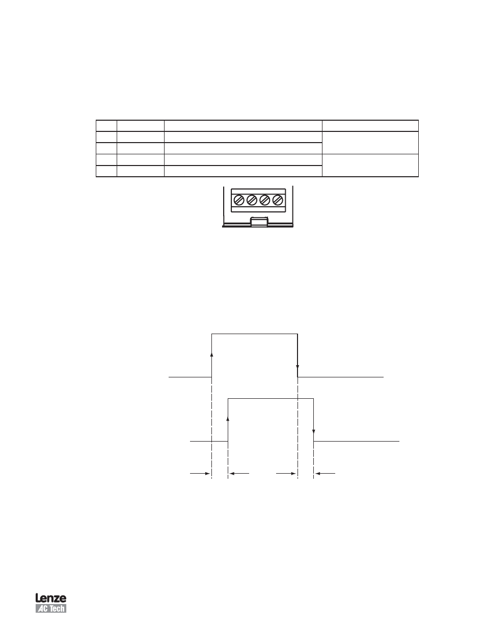
3.2 J1 - Terminal Block
The J1 terminal block consists of 4 terminals at the base of the E94ZAHBK Motor Brake Module The two left
terminals are for the external 4 VDC power supply that will energize the brake coil The two terminals on the
right are to be wired to the brake coil Table lists the Terminal pins from right to left looking at the module,
numbered 1 to 4
Table : J1 Terminal Block Pin Assignment
Pin
Name
Function
Important
1
4 VDC +
4V DC Power Source
4 VDC (0%…+15%)
4 VDC -
4V DC Power Source Return
3
Brake +
Connection to the Brake Coil (+)
max continuous current: 1 5 A
4
Brake -
Connection to the Brake Coil (-)
+ – + –
24VDC BRAKE
1
3
4
2
Figure : J1 Terminal Block
4
Operation
There are two methods of utilizing this module The first is by assigning Ouput to the special purpose function
“
Brake”, see section 5 of the PositionServo Users Manual This will automatically turn the output on when
the drive is enabled and turn the output off when the output is disabled The typical time sequence is shown
in Figure 3
60
µs
60
µs
ENABLE
DISABLE
RELEASED
ENGAGED
ENABLE / DISABLE
BRAKE
Figure 3: Time Sequence
The second method is to use the indexer program to toggle OUT The delay times for releasing and engaging
the holding brake can be controlled with some flexibility
The Motor Brake Module is optically isolated from the PositionServo drive When the output is on, the brake will
be released and the green LED on the module will be illuminated