3connections, 1 p3a - controller interface – Lenze E94P v2.0 User Manual
Page 5
5
P940HBK01B
3
Connections
3.1 P3A - Controller Interface
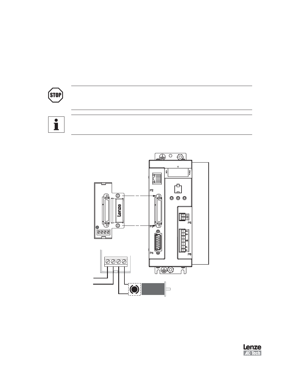
The E94ZAHBK Motor Brake Module is mounted to the P3 connector on the face of the PositionServo drive
as illustrated in Figure 1 The P3A connector on the Brake Module is a pass-through SCSI connector from P3
except for pins 45 and 46
Refer to the PositionServo Users Manaual, Section 5 1 3 for the P3 Pin Assignments
Output (Pins 45 and 46) are dedicated for controlling the Motor Brake on the E94ZAHBK module
STOP!
Pins 45 and 46 on the SCSI connector P3A are dedicated to the control of the holding brake and are
brought out to the terminal block DO NOT USE these pins on the SCSI connector without first consulting
a Lenze / AC Tech Application Engineer
Note
Do not use E94ZAHBK1 with the I/O Simulator module (E94ZATST1) The I/O Simulator uses OUT (Pins
45 and 46) for another purpose
The P3A connector is for interfacing to front-end controllers It is strongly recommended that OEM cables be
used to aid in satisfying CE requirements Contact your PositionServo representative for assistance
24 VDC
–
+
+ – + –
BRAKE
RELEASED
+ – + –
24VDC BRAKE
MOTOR BRAKE
MODULE
Figure 1: Installation of Motor Brake Terminal Module
•
•