2 process input data configuration, Process input data configuration, Process data transfer – Lenze E82ZAFPC010 User Manual
Page 48
Process data transfer
Lenze device control
Process input data configuration
l
48
EDS82ZAFPC010 EN 4.0
7.1.2
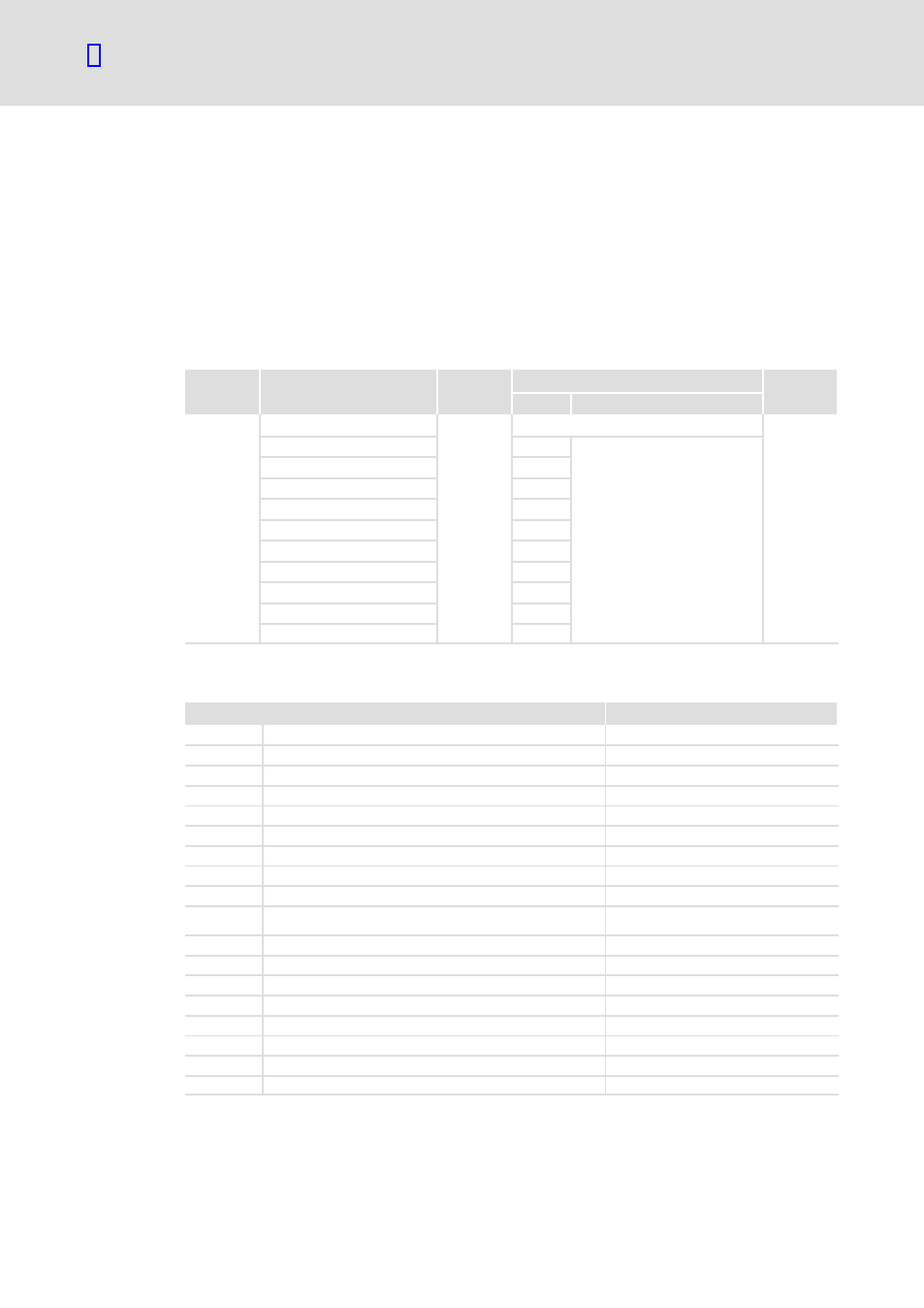
Process input data configuration
The assignment of the bit status information or the actual controller values to the up to 10
process data input words (PIW) of the master can be freely configured:
ƒ
To call DRIVECOM−conform status information, assign the DRIVECOM status word to
a PIW (C1511/x = 18).
The FIF status word 1 is mapped to the DRIVECOM status word.
C1510:
Configuration of process input data
Code
Subcode
Index
Possible settings
Data type
Lenze
Selection
C1510
23065
d
=
5A19
h
FIX32
1 (PIW1)
18
See table below
2 (PIW2)
3
3 (PIW3)
4
4 (PIW 4)
5
5 (PIW 5)
6
6 (PIW 6)
7
7 (PIW 7)
8
8 (PIW 8)
9
9 (PIW 9)
10
10 (PIW 10)
11
The bit status information or the actual values of the controller can be freely assigned to
the max. 10 process data input words (PIW) of the master.
Selection
Scaling
1
FIF status word 1 (FIF−STAT1)
16 bits
2
FIF status word 2 (FIF−STAT2)
16 bits
3
Output frequency with slip (MCTRL1−NOUT+SLIP)
±24000
º ±480 Hz
4
Output frequency without slip (MCTRL1−NOUT)
±24000
º ±480 Hz
5
Apparent motor current (MCTRL1−IMOT)
2
14
º 100 % rated device current
6
Actual process controller value (PCTRL1−ACT)
±24000
º ±480 Hz
7
Process controller setpoint (PCTRL1−SET)
±24000
º ±480 Hz
8
Process controller output (PCTRL1−OUT)
±24000
º ±480 Hz
9
Controller load (MCTRL1−MOUT)
±2
14
º±100 % rated motor torque
10
DC−bus voltage (MCTRL1−DCVOLT)
16383
º 565 V DC for 400 V mains
16383
º 325 V DC for 230 V mains
11
Ramp function generator input (NSET1−RFG1−IN)
±24000
º ±480 Hz
12
Ramp function generator output (NSET1−NOUT)
±24000
º ±480 Hz
13
FIF−OUT.W1
16 bits or 0 ... 65535
14
FIF−OUT.W2
16 bits or 0 ... 65535
15
FIF−OUT.W3
0...65535
16
FIF−OUT.W4
0...65535
17
DRIVECOM control word (DRIVECOM−CTRL)
16 bits
18
DRIVECOM status word (DRIVECOM−STAT)
16 bits