Mechanical installation – Lenze CS 9000 DVI Operating Instructions User Manual
Page 29
Mechanical installation
Mounting steps
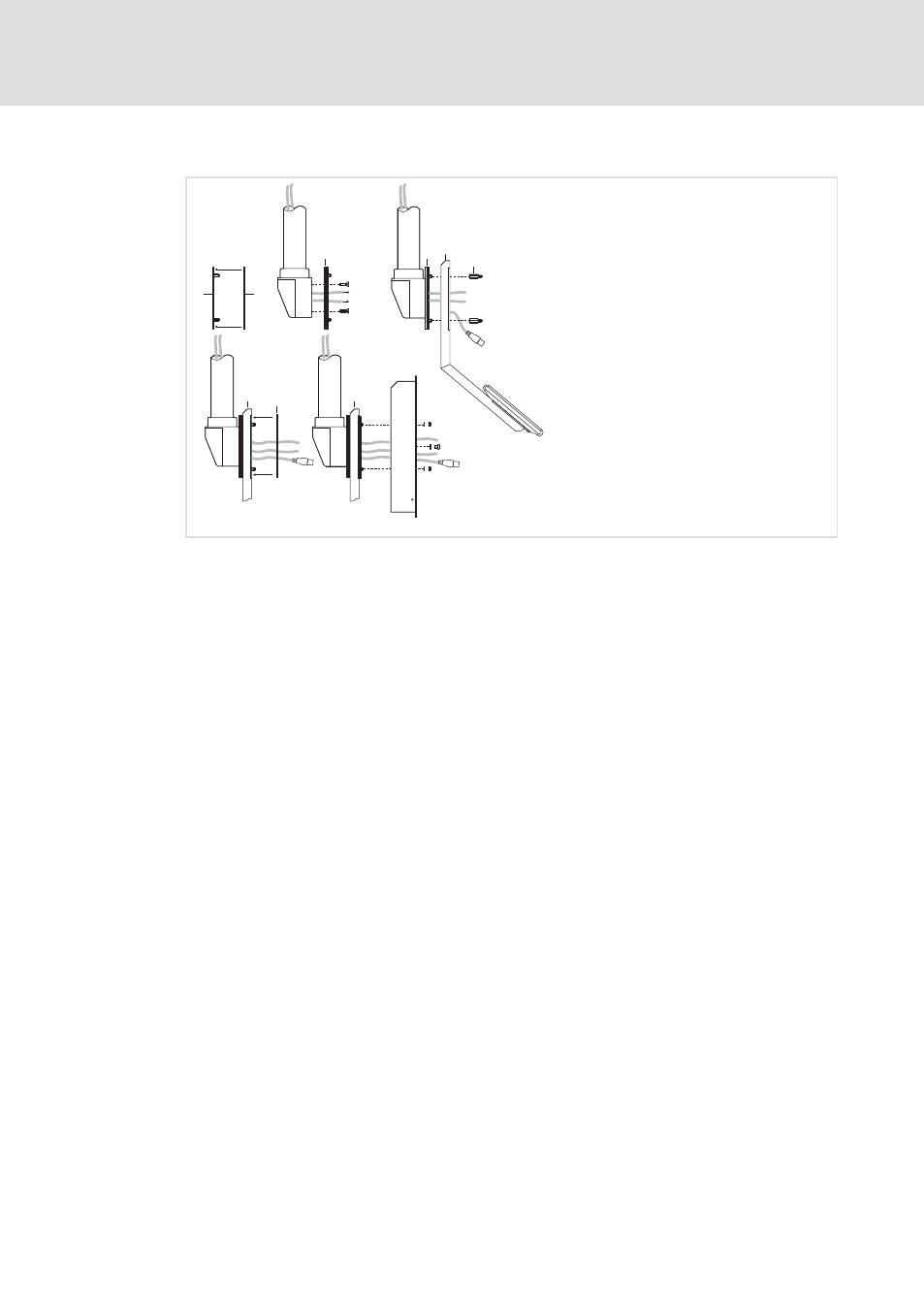
Fixing the mounting frame to the support arm
l
29
BA_CS9000DVI EN 4.0
With add−on component
1
0
1
3
6
4
5
2
1
4
0
4
CS57x0−006
How to proceed:
1. Check support arm system for professional mounting and sufficient carrying
capacity.
– See support arm documentation.
2. Stick the self−adhesive seal
0 on the adapter plate 1 on the side with the threaded
bolts.
3. Pull the connecting cables
2 out of the support arm 3 and screw the adapter plate 1
to the support arm
3.
– For screws see support arm documentation.
4. Screw the add−on component
4 to the threaded bolts of the adapter plate 1.
– 4 spacer bolts
5 on the inside/outside M5 x 20 mm
5. Stick the second self−adhesive seal
0 on the add−on component 4.
6. Screw the mounting frame
6 to the add−on component 4.
– 4 nuts M5 with washers
Æ 5.3 mm
– 4 screws M5 x 8 mm with washers
Æ 5.3 mm
Now you can connect the Command Station (
¶ 33).