Bush Hog CBH80 User Manual
Page 30
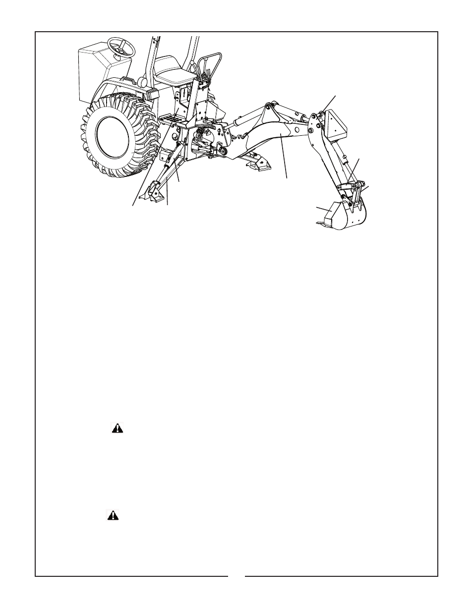
ASSEMBLY - CBH 60, CBH 70, CBH 80
The backhoe has been partially disassembled and
strapped to a skid for shipping purposes. Initial
installation on the tractor will require a hoist or other
device capable of safely lifting the entire backhoe
from the skid. After the initial installation is com-
plete, the backhoe can serve as its own erecting
hoist, by lowering stabilizers and bucket to the
ground. Additional lifting devices will not be required
for normal removal and reattaching.
IMPORTANT: Tighten all hardware to torque
requirements specified in torque chart.
1, Remove the stabilizer assemblies and any mis-
cellaneous items which have been fastened to the
skid and arrange conveniently.
Reposition stabilizer cylinders from their shipping
configuration by assembling them into the main-
frame, using pins and hardware provided. Be sure
cylinder ports are pointed upward and hoses are
routed above the cylinder to mainframe pivot pin
connection.
2. Support boom and dipperstick with hoist and
remove boom transport lock pin. Lower boom and
manually extend dipperstick until it rests on ground.
Move control handle to “BOOM DOWN” position as
required to aid movement.
Model CBH 60
3. Remove plastic bag containing bucket pins from
backhoe. Attach bucket to dipperstick using one pin,
bolt, lock nuts, and shims as needed to take up gap
between dipperstick and bucket.
Model CBH 70
3. Remove plastic bag containing bucket pins from
backhoe. Attach bucket to dipperstick using one
pivot pin, two 5/16 NF x 7/8” bolts, lock nuts, pin
retainers and washers as needed to take up gap
under pin retainers. Place shims between dipper-
stick and bucket as needed to take up gap.
Model CBH 80
3. Remove plastic bag containing bucket pins from
backhoe. Attach bucket to dipperstick using one pin,
two bolts, nuts, lockwashers, pin retainers and
washers as needed to take up gap under pin retain-
ers. Place shims between dipperstick and bucket as
needed to take up gap.
4.Attach bucket link to bucket, using same hardware
as listed from step #3.
5. Reposition hoist to backhoe to prevent tipping.
Remove all remaining strapping and attach stabiliz-
ers to mainframe using pins and hardware assem-
bled to backhoe.
6. Attach stabilizer cylinders to stabilizers using pins
and hardware assembled to stabilizers.
7. Using caution to prevent tipping, raise mainframe
with hoist to a height of approximately 13” and
remove skid. Block mainframe and swing frame
securely.
8. Follow the Attaching Kit Assembly Instructions to
mount the backhoe to the tractor. Check the installa-
tion carefully and make sure that all members are
correctly installed and securely fastened.
!
!
CAUTION
DO NOT cut any strapping that fastens the
backhoe mainframe and swing frame to the
skid base at this time.
Be sure hoist being used is suitable, has
sufficient capacity and is in the proper
position. Do not allow anyone under a
backhoe member supported by hoist.
DIPPERSTICK
GUIDE LINK
BUCKET LINK
BUCKET
BOOM
STABILIZER
CYLINDER
STABILIZER
LEG
MAINFRAME
!
!
CAUTION
28
Figure 13