Engine guard mount driving lights, Installation – Kuryakyn 5019 ENGINE GUARD MOUNT DRIVING LIGHTS User Manual
Page 4
PAGE
4
It is the installer’s responsibility to ensure that all of the fasteners (including
pre-assembled) are tightened before operation of the motorcycle.
Küryakyn will not provide warranty coverage on products or
components lost due to improper installation or lack of maintenance.
Periodic inspection and maintenance are required on all fasteners.
FOR UNIVERSAL WIRING ON OTHER MODELS
STEP 17
Using a test light or wiring schematic, with the key in the “ON” position, locate a
“keyed” (has power with the key “ON”, loses power with the key “OFF”) 12-volt
power wire to power the driving lights. Once you have located a keyed 12-volt
power source, turn the key to the “OFF” position and disconnect the battery.
Avoid potential electrical shock! Disconnect the battery
before starting this procedure.
Kuryakyn recommends the use of dielectric grease on electrical
connections.
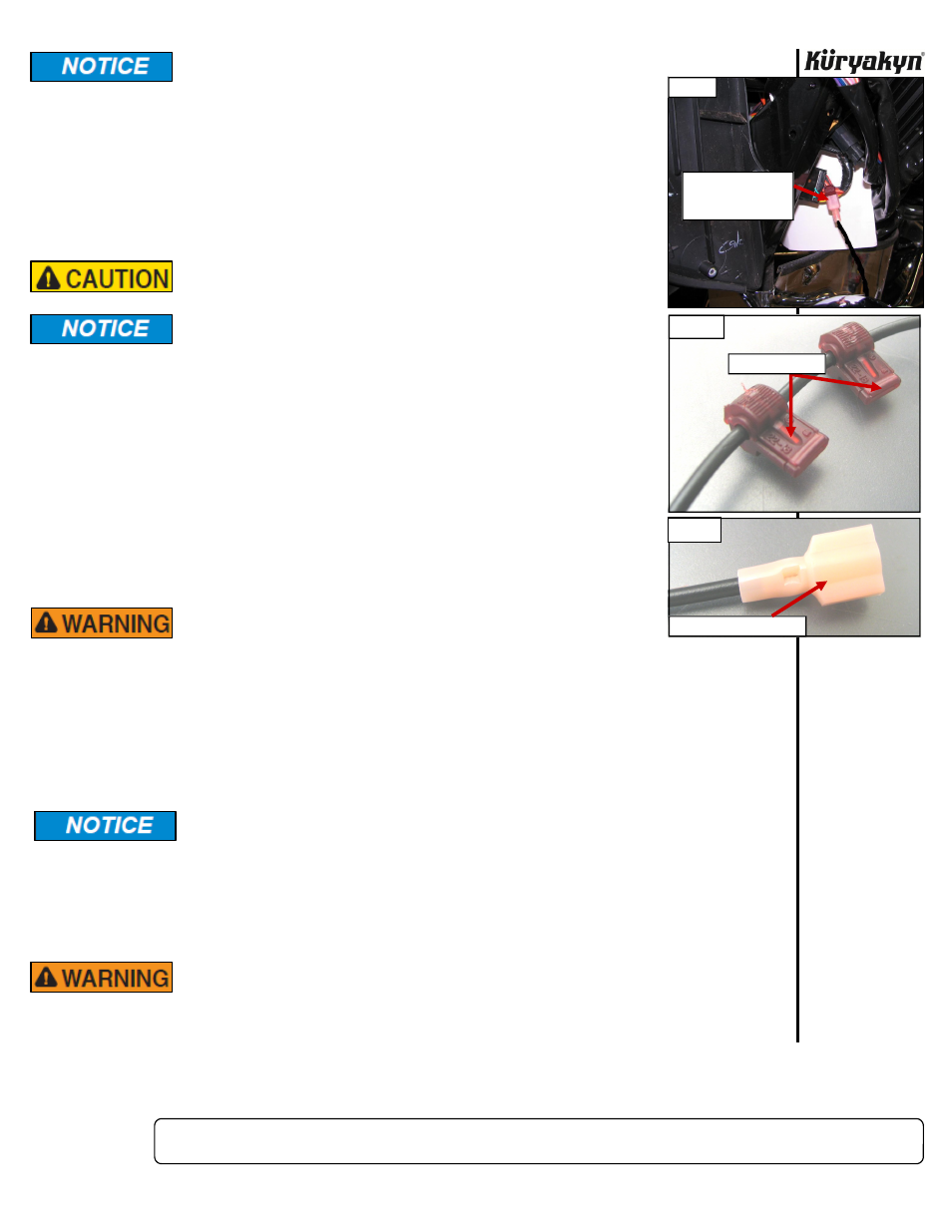
STEP 18
Once you have located a keyed 12-volt power source, take the two female T-Tap
connectors and place them on the desired power wire. PIC 10
STEP 19
Take the black power wires and cut them to desired length, strip the ends and
place a male Spade Connector on it and crimp. PIC 11
STEP 20
Place a small amount of dielectric grease on the female T-Tap connectors and
insert the male spade connectors the female T-Tap connectors installed on the
keyed power wire. These driving lights are self-grounding so you will not need to
hook up any negative leads.
STEP 21
Once all connections are connected, turn the key to the “ON” position and check
to ensure the lights work properly.
ENSURE PROPER LIGHT OPERATION BEFORE RIDING THE
MOTORCYCLE. VISIBILITY IS A MAJOR CONCERN FOR
MOTORCYCLISTS. A LIGHTING MALFUNCTION COULD
RESULT IN DEATH OR SERIOUS INJURY.
STEP 22
If lights do not work, go over the wire connections and check all plugs to see if they are
plugged-in correctly. You may also have to use a test light again check if the spade/T-Tap
connectors are in the proper locations.
STEP 23
When you are satisfied with all the wiring, you can use the supplied cable ties and secure the
wires out of harms way.
Secure all wiring from the newly installed and/or from existing parts, away from
any moving parts, pinch points or extreme heat. Küryakyn WILL NOT issue a
warranty on any electrical component that fails due to pinched, crimped, broken,
abraded, melted or frayed wires.
STEP 24
To aim the driving lights simply loosen the bottom 3/8”-16 Nylon Chrome Nut and point to the
desired location. Retighten the 3/8”-16 Nylock Chrome Nut and repeat the same process for the
opposite
side.
IT IS THE INSTALLERS RESPONSIBILITY TO ADJUST THE NEW DRIVING
LIGHTS TO THE PATTERN RECOMMENDED IN THE SERVICE MANUAL FOR
THE HEADLIGHT LOW BEAM. FAILURE TO PROPERLY ADJUST THE LIGHT
PATTERN MAY DISTRACT ONCOMING DRIVERS RESULTING IN SERIOUS
INJURY OR DEATH.
ENGINE GUARD MOUNT DRIVING LIGHTS
INSTALLATION
PIC 10
FEMALE T-TAPS
MALE SPADE CONNECTOR
PIC 11
BLACK POWER WIRE
CONNECTED TO
SECOND ORANGE
PIC 9
-cont.-