Engine guard mount driving lights, Installation – Kuryakyn 5019 ENGINE GUARD MOUNT DRIVING LIGHTS User Manual
Page 3
PAGE
3
STEP 7
Repeat assembly on the opposite side of the engine guard. Make sure wire is not pinched and can
move
freely.
PIC
6
TURN THE FORK LOCK TO LOCK TO CHECK FOR
CLEARANCE BETWEEN THE LIGHTS AND ANY OTHER
COMPONENT ON THE MOTORCYCLE. INSUFFICIENT
CLEARANCE MAY CAUSE LOSS OF CONTROL RESULTING
IN SERIOUS INJURY OR DEATH.
Avoid potential electrical shock! Disconnect the battery
before starting this procedure.
FOR ‘97 and LATER ELECTRA GLIDE AND STREET GLIDE
MODELS, ALL OTHER MODELS PROCEED TO STEP 17
STEP 8
Remove the outer fairing and windscreen as outlined in the service manual for
your
bike.
Remove
the
seat and disconnect the battery.
STEP 9
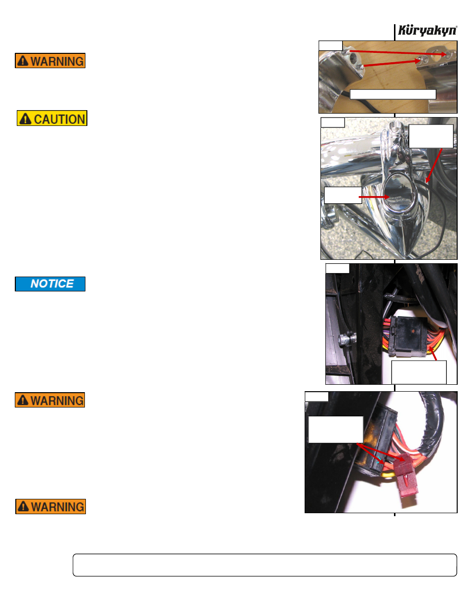
Locate the black wiring connector that has the accessory wires in it. This is
usually located on the throttle side of the inner fairing. PIC 7
STEP 10
Using the ORANGE wire that is second in from the end (#2 pin terminal),
install one of the included Female T-Tap connectors to this wire. PIC 8
STEP 11
Take the end of one of the BLACK power wires from one of the Driving Lights
and crimp on one of the included Male Spade connectors. Connect this wire to
the Female T-Tap installed on the ORANGE wire in STEP 10. PIC 9-Page 4 This
wire is powered when the Accessory switch is turned on.
Kuryakyn recommends the use of dielectric grease on electrical
connections.
STEP 12
Install one of the included Female T-Tap connectors to the BLACK power wire,
from STEP 11, approximately two inches from the connection into the Female
T-Tap on the ORANGE wire from STEP 11. This will be the power for the other
light.
STEP 13
Crimp a Male Spade connector to the end of the other Driving Light BLACK
power wire. Connect this to the Female T-Tap installed in STEP 12.
STEP 14
Once all connections are connected, reconnect the battery, turn the key to the
“ON” position and check to ensure the lights work properly.
ENSURE PROPER LIGHT OPERATION BEFORE RIDING
THE MOTORCYCLE. VISIBILITY IS A MAJOR CONCERN
FOR MOTORCYCLISTS. A LIGHTING MALFUNCTION
COULD RESULT IN DEATH OR SERIOUS INJURY.
STEP 15
If lights do not work, go over the wire connections and check all plugs to
see if they are plugged-in correctly. You may also have to use a test light
again
to
check if the spade/T-Tap connectors are in the proper locations.
STEP 16
Reinstall the outer fairing and windscreen as per the service manual.
Replace
the
seat.
AFTER INSTALLING THE SEAT, PULL UP ON IT TO
ENSURE IT IS LOCKED INTO PLACE. A LOOSE SEAT
CAN SHIFT AND CAUSE LOSS OF CONTROL RESULTING IN SERIOUS
INJURY OR DEATH.
ENGINE GUARD MOUNT DRIVING LIGHTS
INSTALLATION
PIC 5
PIC 5
MAKE SURE PINS GO INTO HOLES
PIC 6
CLAMP CAP
INSTALLED
MAKE SURE
WIRE MOVES
FREELY
USE THE SECOND
ORANGE WIRE IN
THIS CONNECTOR
PIC 7
FEMALE T-TAP ON
SECOND ORANGE
WIRE
PIC 8
-cont.-