Engine guard mount driving lights, Installation – Kuryakyn 5019 ENGINE GUARD MOUNT DRIVING LIGHTS User Manual
Page 2
PAGE
2
NOTE:
Kuryakyn recommends using one of our Driving Light and Switch/Relay
Harnesses, P/N 2202 or P/N 2328, to power the lights to
prevent overloading a circuit on the bike. We have included
instructions to on how to connect these lights to an unused
Accessory
switch
on
Electra
Glide
and
Street
Glide
models
or
you may install the black power wires from the driving lights
using the female t-tap connectors and connect them to a
“keyed” power source. The lights draw approximately 6 amps.
Before connecting the power wires to a circuit check to make
sure that the circuit can handle the additional load.
YOU WILL BE WORKING AROUND THE ENGINE AND
EXHAUST SYSTEM DURING INSTALLATION. ENSURE
THAT THE ENGINE AND EXHAUST SYSTEM HAVE FULLY
COOLED TO PREVENT INJURY.
IT IS THE INSTALLERS RESPONSIBILITY TO ENSURE THAT
THE INSTALLATION OF THIS ACCESSORY DOES NOT
EXCEED THE MAXIMUM AMPERAGE OF THE CHOSEN
CIRCUIT. EXCEEDING THE MAXIMUM ALLOWABLE
AMPERAGE MAY LEAD TO CIRCUIT FAILURE WHICH
COULD RESULT IN SERIOUS INJURY OR DEATH.
A FACTORY SERVICE MANUAL WILL BE HELPFUL IN
PERFORMING THIS INSTALLATION. DO NOT ATTEMPT TO
PERFORM THIS INSTALLATION IF YOU ARE NOT
CONFIDENT IN YOUR ABILITY TO COMPLETE ALL OF THE
STEPS IN THE PROCEDURE; CONSULT A TRAINED
TECHNICIAN. IMPROPER INSTALLATION COULD RESULT
IN SERIOUS INJURY OR DEATH.
STEP 2
Remove the two #10-24 X 1/2” socket head cap screws from each clamp.
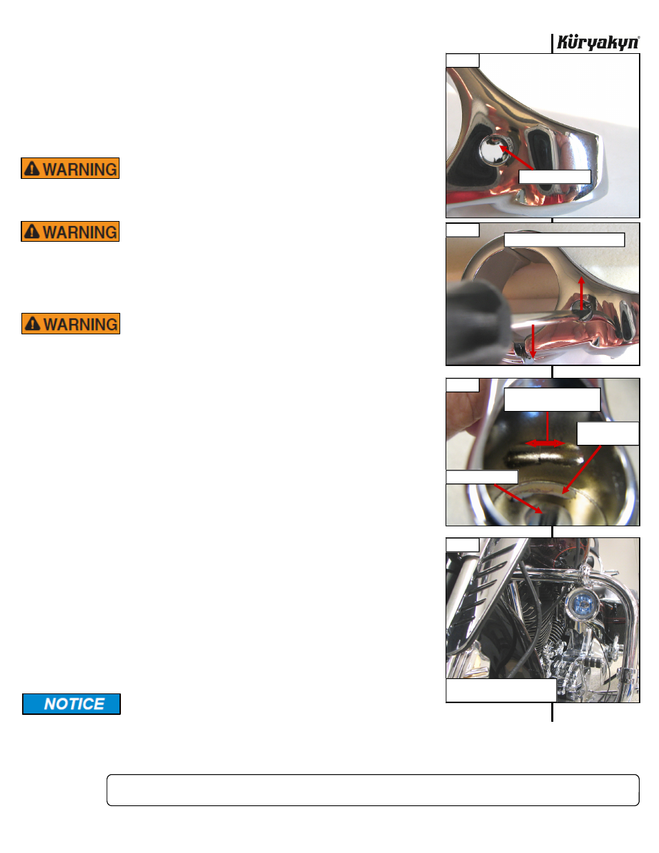
STEP 3
Looking into the wire exit location in either side of the rear clamp half, find
the tab of the clamp cap. PIC 1 Insert a small screwdriver or pick tool in the
hole and gently pry up. PIC 2 (DO NOT try to pry up from the outside edge of
the clamp cap, you will damage it.) This will push the tab up and release the
cover for access to the hex nut.
STEP 4
Determine which side of the clamp you would like the power wire to exit from
and route the wire through the clamp. PIC 3
STEP 5
Place the driving light stud through the mounting clamp and secure it with the
provided
3/8”-16
Nylock Hex Nut. Leave finger tight for now.
STEP 6
The placement of the Driving Lights on top of the engine guard is up to the
installer for best lighting pattern. PIC 4 Mount the driving light to the engine
guard in the desired location. Make sure the pins on the back clamp go into
the holes on the front clamp. PIC 5 Tighten securely. Install the clamp caps in
the clamps. PIC 6
NOTE:
If you need to remove the clamp caps once installed, repeat Step 3.
Insert the tool in the open side opposite the wire, to gently pry up on
the
lock
tab.
Secure all wiring from the newly installed and/or from existing
parts, away from any moving parts, pinch points or extreme
heat. Küryakyn WILL NOT issue a warranty on any electrical component that fails
due to pinched, crimped, broken, abraded, melted or frayed wires.
ENGINE GUARD MOUNT DRIVING LIGHTS
INSTALLATION
-cont.-
ROUTE WIRE
THROUGH
GROOVE IN
BACK CLAMP
HALF
PIC 4
PIC 3
WIRES MAY EXIT EITHER
SIDE THROUGH HERE
INSERT STUD HERE
INSERT WIRE
THROUGH SLOT
PIC 1
PIC 2
TAB ON CLAMP CAP
GENTLY PRY UP TO RELEASE CAP
PLACEMENT ON TOP OF BAR
IS UP TO THE INSTALLER