Chapter, Installation – Koolance RP-1250-R User Manual
Page 9
10
11
User Manual
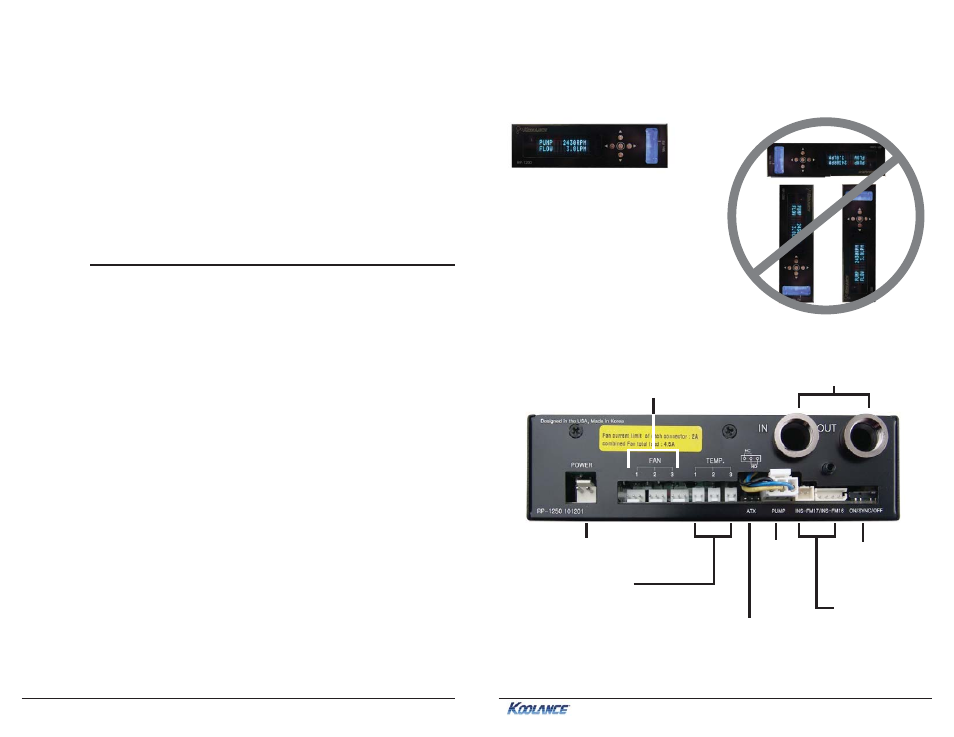
Positioning the Unit
The cooling unit is designed to operate in one orientation. In other directions, the
pump and reservoir may not bleed properly and could lead to cavitation.
YES
NO
Installation
Chapter
2
Installation
Reservoir & Pump Connections
POWER
: Connection from
power supply, 12VDC
FAN
: Radiator fan connections
(2.0A max per plug, 4.5A total)
TEMP
: Temperature sensors
shown on the front display
IN/OUT
: Liquid fitting sockets
The rear of the unit accepts various connections to integrate with your cooling
system.
PUMP
:
Internal
pump
INS-FM17/INS-FM16
:
Connect an optional
flow meter to display
flow rate
ON/SYNC/OFF
:
Adjusts LED lighting
of INS-FM16 flow
meter
ATX
: Wire lead for safety shutdown relay. For computer use,
leave the 2-pin wire connected to “NO” (Normally Open) pins.
If this unit’s relay feature (see: “Alarm and Shutdown Settings”,
pg.4) will be used for an application requiring a Normally Closed
circuit, move wire lead to “NC”.