Erm-2k3u system diagram, Led display panel – Koolance ERM-2K3UCU User Manual
Page 6
4
5
User Manual
Introduction
ERM-2K3U System Diagram
Reservoir
Rear Radiator
Cooling Fans
Radiator
(Primary Heat Exchanger)
Radiator -
The primary heat exchanger is the main cooling element, and provides
high thermal dissipation in a relatively small area. Inside, an aluminum mesh
(louver fin) is webbed between horizontal liquid paths.
Reservoir & Pump -
The coolant tank is transparent for easy liquid-level monitoring
through the front window. It is filled through a small metal plug on the side. Lighting
for the reservoir can be toggled with the rear Illumination Switch.
Pump
Outlet
Inlet
9-pin Plug (Sensors)
Reservoir Illumination Switch
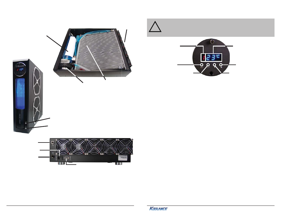
LED Display Panel
Modes
The
ERM-2K3U
offers seven display options. All are reached by continually
pressing the SET button:
1. Temperature sensor #1 is displayed
2. Temperature sensor #2 is displayed
3. Temperature sensor #3 is displayed
4. All temperature sensors are cycled automatically
5. Fan setting is displayed (“F” is shown as the mode)
6. Pump setting is displayed (“P” is shown as the mode)
7. All temperatures, fan, and pump settings are cycled automatically
Temperature Sensors
ERM-2K3U
systems can monitor up to 3 temperature sensors (included). The first
LED digit indicates which sensor channel is currently displayed in the temperature
reading. To cycle through sensors, press SET.
Fan Speed
This option adjusts the radiator fan speed. Higher speeds can improve performance,
but will produce more noise. There is 1 automatic and 10 manual fan settings (1-
10). From the fan (“F”) or any cycle mode, press the
▼ or ▲ buttons to adjust fan
settings, or hold down an arrow to skip to the lowest or highest mode directly.
Automatic mode will adjust the fans for you based on temperature values from
sensor #1. This mode is reached by lowering the fan setting to “0” (Aut / A will
be displayed).
Pump Speed
There are 10 manual pump settings (1-10). From the pump (“P”) mode, press
CAUTION:
ERM systems allow full user control of hardware safety
settings, such as audio alarm, shutdown, and pump speed. Please be
sure to configure your LED Display Panel properly, or damage to your
computer, data, and/or equipment could result.
!
Current Mode
Value
Mode Select
Display in ºC or ºF
Decrease Setting
Increase Setting
Power Plug
Power Button