Kds milliliter oem module, Appendix e: optional – daisy-chaining – KD Scientific 910 OEM Pump User Manual
Page 21
Appendix E: Optional – Daisy-Chaining
The RS-232 Connection to the first board in the daisy-chain is made through the 9-pin D-Sub
connector or RJ-11 input (J1). Use an appropriate adapter to connect a 9-pin or 25-pin D-
Sub at a PC to the RJ-11 input. A straight-through RJ-11 to RJ-11 cable is used to connect
from the RJ-11 output (J2) of the first board to the input of the next board in the daisy-chain.
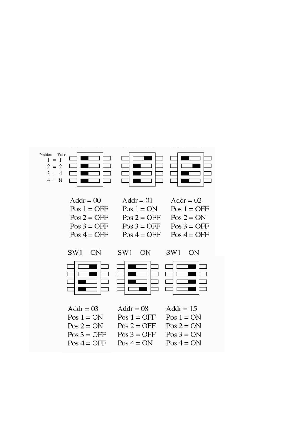
Set each board in the chain to be at a unique address (00 to 15) by setting the DIP switch-
es (SW1) as follows:
Fig. 1 - 5 Examples of the 16 Possible Address Configuration Settings
To communicate with each board in the daisy-chain, prefix commands and queries with the
address. Addresses must be two digits (i.e. 00 to 15). These addresses are based on the
principle of binary notation. Add up your address value by moving the appropriate switch
to the “on” position.
**Pump must be power-cycled or reset for address change to be recognized.**
KDS Milliliter OEM Module
22