JUMO 902520 Indoor and Outdoor RTD Temperature Probe Data Sheet User Manual
Page 2
2011-05-20/00311507
Data sheet 90.2520 (90.2523)
Page 2/7
JUMO GmbH & Co. KG
Delivery address:Mackenrodtstraße 14,
36039 Fulda, Germany
Postal address: 36035 Fulda, Germany
Phone:
+49 661 6003-0
Fax:
+49 661 6003-607
e-mail:
Internet:
www.jumo.net
JUMO Instrument Co. Ltd.
JUMO House
Temple Bank, Riverway
Harlow, Essex CM20 2DY, UK
Phone: +44 1279 635533
Fax:
+44 1279 635262
e-mail:
Internet: www.jumo.co.uk
JUMO Process Control, Inc.
8 Technology Boulevard
Canastota, NY 13032, USA
Phone:
315-697-JUMO
1-800-554-JUMO
Fax:
315-697-5867
e-mail:
Internet: www.jumo.us
1. All specifications referring to the measuring range limit value of 20mA. 2. The higher value is valid.
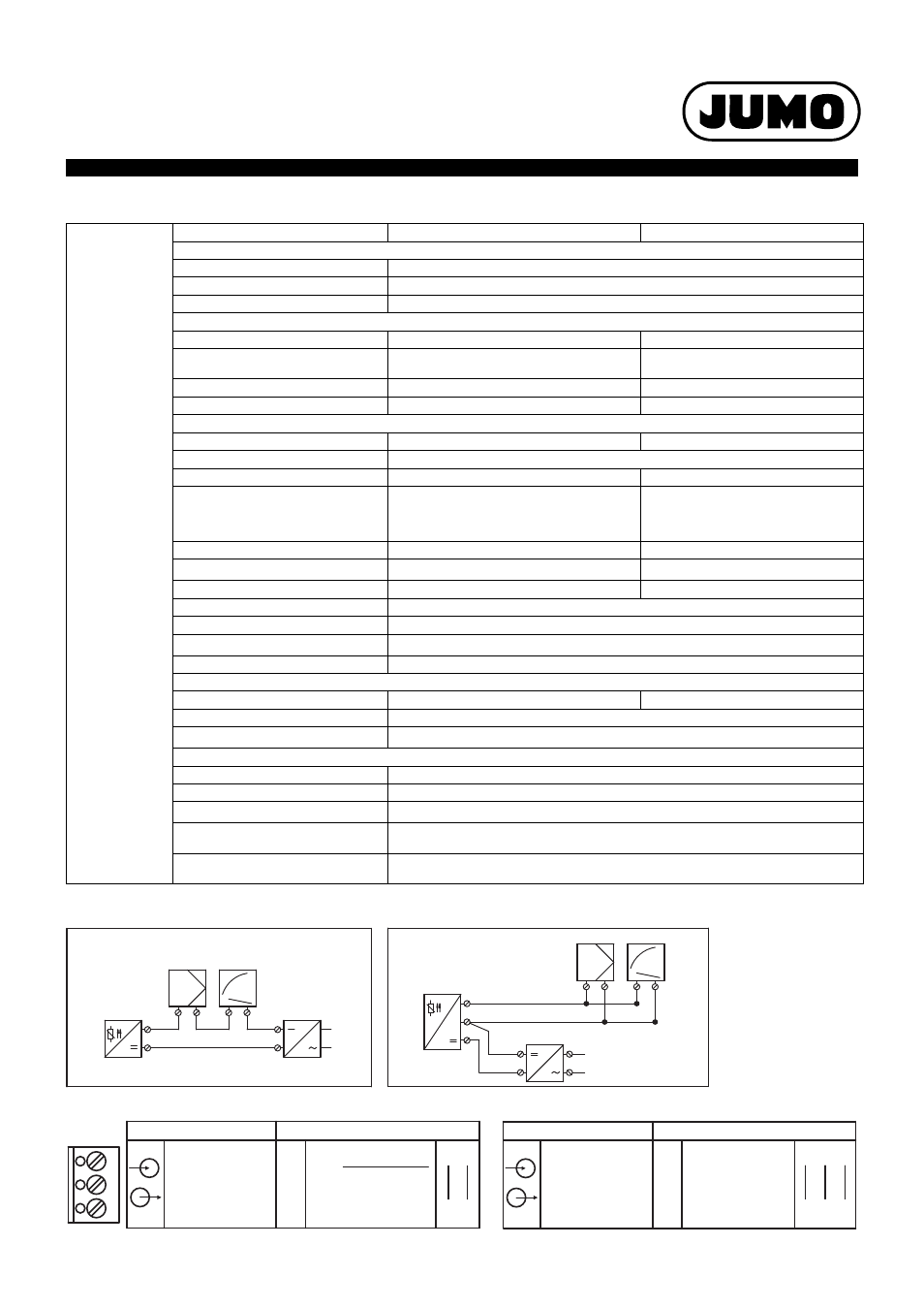
Connection example with power pack, output 4 ... 20 mAConnection example with power pack, output 0 ... 10 V
Connection diagram
Transmitter
Output 4 ... 20 mA
Output 0 ... 10 V
Input
Measuring input
Pt100 (DIN EN 60751)
Probe current
≤
0.5 mA
Measuring range
Permanent measurement due to analog signal path
Measuring circuit monitoring
Underrange
dropping to
≤
3.6 mA
0 V
Overrange
increasing to
÷
22 mA ... < 28 mA (typical
24 mA)
increasing to
÷
11 V ... < 14 V
(typical 12 V)
Probe short-circuit
≤
3.6 mA
0 V
Probe and wire break
÷
22 mA ... < 28 mA (typical 24 mA)
÷
11 V ... < 14 V (typical 12 V)
Output
Output signal
load-independent direct current 4 ... 20 mA
Direct current 0 ... 10 V
Transmission behavior
temperature linear
Transmission accuracy
≤
± 0.1 %
≤
± 0.2 %
Damping of the residual ripple
of a voltage supply of 24 V,
amplitude 10 V/50 Hz,
burden 470
Ω
/Load 10M
Ω
37 dB
40 dB
Burden (Rb)
Rb = (Ub - 7.5 V) / 22 mA
-
Burden influence
≤
± 0.02 % / 100
Ω
1
-
Load/load influence
-
÷
10 k
Ω
/
≤
± 0.1 %
Setting time for temperature changes
≤
10 ms
Adjustment conditions
DC 24 V / approx. 22 °C
Calibration accuracy
≤
± 0.2 %
1,2
or
≤
± 0.2 K
Overall accuracy, probe/calibration
± 0.4 K (typical) at 20 °C / 24 V voltage supply
Voltage supply
Voltage supply (Ub)
DC 7.5 ... 30 V
DC 15 ... 30 V
Reverse voltage protection
yes
Voltage supply influence
≤
± 0.01 %/V deviation from 24 V
1
Environmental influences
Operating temperature range
-40 ...+ 85 °C
Storage temperature range
-40 ... +100 °C
Temperature coefficient
≤
± 0.01 %/K deviation from 22 °C
1
Ambient conditions
similar to DIN EN 60654 Kl. C1
relative humidity
≤
95 % annual average, no condensation
EMC Interference emission/
resistance
EN 61326 class B/Industrial requirements
-
+
+
-
+
-
+
-
4 - 20mA
Indicator
Controller
2-wire
transmitter
Supply unit
7.5 - 30V DC
+
-
-
+
+
-
-
+
0 - 10V
Indicator
Controller
3-wire
transmitter
Supply unit
15 - 30V DC
+
0 - 10V
L1
N
81
83
82
15 - 30V DC
Supply voltage
Terminal
Connection for
Voltage output
0 - 10V
+ 81
- 82
- 82
+ 83
81
+
83
+
Load
10k
≥
Ω
Output 0 - 10V
82
-
Output 4 - 20mA
22mA
- 7.5V
b
U
B
R =
R
B
= burden resistance
b
= supply voltage
U
-
82
+
81
- 82
+ 81
Current output
4 - 20mA
Supply voltage
7.5 - 30V DC
Terminal
Connection for