Technical data – JUMO 60.8520 Contact dial thermometer Data Sheet User Manual
Page 2
2011-04-14 / 00304658
Data sheet 608520
Page 2/12
JUMO GmbH & Co. KG
Delivery address: Mackenrodtstraße 14
36039 Fulda, Germany
Postal address:
36035 Fulda, Germany
Phone:
+49 661 6003-0
Fax:
+49 661 6003-607
E-mail:
Internet:
www.jumo.net
JUMO Instrument Co. Ltd.
JUMO House
Temple Bank, Riverway
Harlow, Essex CM20 2DY, UK
Phone: +44 1279 635533
Fax:
+44 1279 635262
E-mail:
Internet: www.jumo.co.uk
JUMO Process Control, Inc.
6733 Myers Road
East Syracuse, NY 13057, USA
Phone: 315-437-5866
1-800-554-5866
Fax:
315-437-5860
E-mail:
Internet: www.jumousa.com
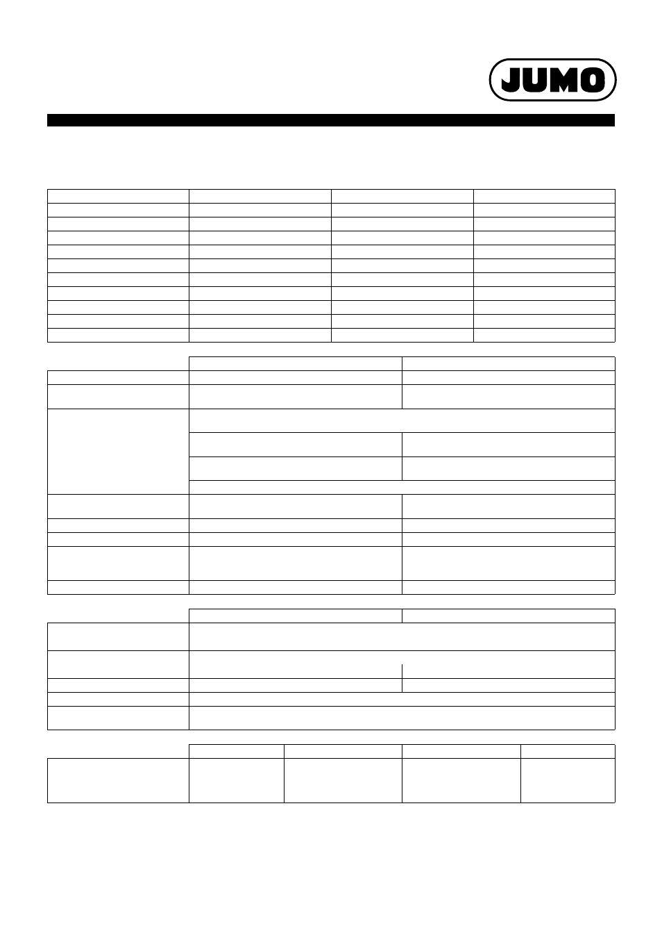
Technical Data
Display range (AB)
Display range in °C
Measuring range in °C
Tolerance in °C
469
-40...+40
-30...+30
1.5
643
-20...+120
-20...+120
3.0
807
0...+60
+10...+50
1.5
814
0...+100
+10...+90
1.5
818
0...+120
+20...+100
3.0
832
0...+200
+20...+180
3.0
840
0...+300
+30...+270
6.0
848
0...+400
+50...+350
6.0
854
0...+500
+50...+450
8.0
848
0...+600
+100...+500
10.0
Liquid filling
Gas filling
Measuring system
Display range (AB)
≤ 350°C
Display range (AB)
÷ 400°C
Time behavior
approx. 12 s, measured in water,
with a probe Ø of 6 mm made of Cu.
approx. 4 s, measured in oil,
with a probe Ø of 10 mm made of stainless steel.
Ambient temperature
influence effect
In % of the display range (referring to the deviation from the reference value +23°C)
on case
0.15% of the display range
per K ambient temperature change
0.05% of the display range
per K ambient temperature change
on capillary (per m)
0.03% of the display range
per K ambient temperature change
no influence
Higher ambient temperature – higher temperature display – lower switching point
Anti-kink spring
for devices with capillary on the case and the tem-
perature probe
Set point value setting
by set point controller in the front window
Display correction
on the rear
Limit value temperatures
for transport and storage -30°C...+70°C
(for display range -40...+40°C up to max. 50°C; -
30...+50°C up to max. 60°C)
Rated position
any
standard
Extra code (TZ) 650
Electric contact
Single-pole microswitch with mechanically actuate change-over contact
Type of contact
Contact rating
AC 230V, +10/-15%, 48...63Hz, cos
ϕ = 1 (0.6)
5 (1.5) A
10 (3) A
Hysteresis
approx. 1.5% of the display range
1.5 to 3% of the display range
Switching point accuracy
± 0.5% of the display range referring to the switch-off point with rising temperature
Switching reliability
To ensure a high switching reliability, we recommend a minimum voltage of
24 V and a minimum current of 100 mA
standard
Design 02 and 22
Design 10, 23 and TZ 426
Case
∅ 60 mm
Electrical connection
Screw-type termi-
nals, connection
cross section up to
2.5 mm
2
Connection cable 0.5 m
with screw-type terminals
Cover cap with cable
screw-connection, suitable
for cable Ø from 6.5 to
13 mm
Cover cap with cable
screw-connection,
suitable for cable Ø
from 8 to 10 mm