Installation, Technical data, Setpoint and limit setting – JUMO 60.3035 Surface-mounting single or twin thermostat, ATH-SW Operating Manual User Manual
Page 2: Loading permissible incident flow velocity, Pocket, Mounting the probe, Electrical connection, Resetting the stb, Self-monitoring
Permissible loading on the pocket
20, 21, 30, 32, 40, 42 and 45 pockets
Steel pocket
Materials:
Tube:
St 35.8 I
Screw-in nipple up to 300°C: 1.0038
Welding nipple:
Steel 1.5415
Loading
Permissible incident flow velocity
A
The values below refer to the maximum loading on the probe mounting
concerned. The actual maximum sealable pressure depends on the mounting
conditions and may possibly be lower.
Temperature
Tube diameter "D"
8 x 0.75 mm
or conical
10 x 0.75 mm
15 x 0.75 mm
maximum permissible pressure
100°C
89 bar
72 bar
48 bar
150°C
83 bar
67 bar
45 bar
200°C
78 bar
63 bar
42 bar
300°C
59 bar
47 bar
32 bar
350°C
50 bar
40 bar
27 bar
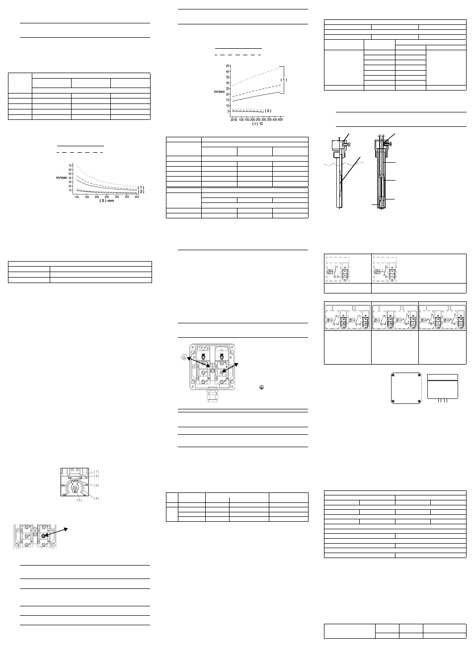
Temperature:
+200°C
Heat carrier:
air ( 1 ), water, oil ( 2 )
Tube diameter "D".
0
8 mm
10 mm
. . . . . . . . . . . . . .
15 mm
Permissible incident flow
velocity (m/sec)
at maximum permitted
pressure loading and
different immersion
tube lengths ( S ).
( 1 ) air
( 2 ) water, oil
( S ) immersion tube length
- permissible incident flow velocity: on request -
A
The values below refer to the maximum loading on the probe mounting
concerned. The actual maximum sealable pressure depends on the mounting
conditions and may possibly be lower.
Immersion tube length
200 mm:
Material: steel
Temperature:
+200°C
Heat carrier:
air ( 1 ), water, oil ( 2 )
Tube diameter "D".
0
8 mm
10 mm
. . . . . . . . . . . . . .
15 mm
Permissible incident flow
velocity (m/sec)
at maximum permitted
pressure loading and
different immersion
tube temperatures ( t ).
( 1 ) air
( 2 ) water, oil
( t ) temperature
Stainless steel
Tube and nipple: X 6 CrNiMoTl 17 122
Temperature
Tube diameter "D"
8 x 0.75 mm
or conical
10 x 0.75 mm
15 x 0.75 mm
maximum permissible pressure
100°C
92 bar
74 bar
50 bar
150°C
88 bar
71 bar
48 bar
200°C
83 bar
67 bar
45 bar
300°C
72 bar
58 bar
39 bar
400°C
67 bar
54 bar
36 bar
Brass
Tube and nipple: CuZn
Temperature
Tube diameter "D"
8 x 0.75 mm
10 x 0.75 mm
15 x 0.75 mm
maximum permissible pressure
100°C
50 bar
40 bar
27 bar
150°C
48 bar
39 bar
26 bar
Probe mountings 50, 52 and 54
(probe in direct contact with medium)
Process connections 10, 15, 21, 31, 60 and 65 must only be used in unpressurized
media.
Mounting the probe
Nipple material
Copper (CuZn)
Steel (St)
Stainless steel (CrNi)
Max. temperature
200°C
300°C
400°C
Probe material
Ø mm
Device function
TW
STB, STW (STB)
Cu-DHP
0
4
0
6 bar
2 bar
0
5
0
5 bar
0
6
0
4 bar
0
7
0
3 bar
0
8
0
3 bar
0
9
0
3 bar
10
0
3 bar
1.4571; St 35
0
4 - 10
10 bar
2 bar
H
The temperature probe ( 2 ) must be fully immersed in the medium,
otherwise there will be appreciable variations in the switching point.
( 1 ) Clamp
( 2 ) Temperature probe
( 3 ) Capillary
( 4 ) Pocket
( 5 ) Spring clip
In the "20" and "22" probe
mountings of thermostats with
capillary, the temperature probe is
held in position by sliding a clamping
clip over the capillary and clamping it
with a screw in the enlarged open
end of the pocket.
With "50, 52, 54, 40, 41, 60 and 65"
probe mountings, the probe is held in
position by the fitting attached to the
capillary at the factory.
( 1 )
( 2 )
( 1 )
( 3 )
( 2 )
( 4 )
( 5 )
5. Installation
Regulations and notes
Electrical connection
Cu capillary tube with PE function
V
■ The electrical connection must only be carried out by qualified personnel.
■ The choice of cable, the installation and the electrical connection must
conform to the requirements of VDE 0100 “Regulations on the Installation of
Power Circuits with Nominal Voltages below 1000 V” and the appropriate
local regulations.
■ If contact with live parts is possible when working on the device, it must be
completely disconnected from the electrical supply.
■ Ground the instrument to the protective earth at the PE terminal. The cross-
section of this cable must be at least the same as that of the supply cables.
Wire the grounding conductors in a star configuration to a common earth
point that is connected to the PE conductor of the electrical supply. Do not
loop the grounding cables, that is, do not run them from one instrument to
another.
■ Apart from faulty installation, incorrect settings on the thermostat may also
adversely affect the proper functioning of the subsequent process or cause
other damage. It should only be possible for qualified personnel to make
these settings. Please observe the relevant safety regulations for such
matters.
H
The instrument complies to Protection
Class I.
1. Remove safety protection.
2. Pass the connection cable
(cable diameter 5 to 10 mm)
through the compression gland ( A ).
Screw connection up to 2.5 mm
2
conductor cross-section.
3. Make the connection to the terminals
( 1, 2 and 4 ), as shown in the relevant
connection diagram.
4. Connect the protective earth conductor
to terminal
"PE" .
5. Replace the safety protection.
6. The reset button ( B )
on the STB must be free to move.
H
The connection is suitable for fixed wiring. Cable entry is without fixed strain
relief. Attachment type "X" (no special tools).
V
With CrNi capillary tubes it is the user's responsibility to provide the requisite
protective measures against electric shock.
( A )
( B )
Connection diagrams
Single thermostats
Twin thermostat
TW, STW (STB)
with changeover contact
STB
with break contact and lock-out
Systems I and II:
with changeover contact
switching function: TW,
STW
System I:
with changeover contact
switching function: TW,
STW
System II:
with break contact and
lock-out switching
function: STB
Systems I and II:
with break contact and
lock-out
switching function: STB
Closing the housing
1. Check that the plastic seal ( 3 )
in the housing base ( 2 )
is correctly seated.
2. Place the top of the housing ( 2 )
onto the base ( 4 )
3. Tighten the cover screws ( 1 ).
( 1 )
( 1 )
( 1 )
( 1 )
( 2 )
( 4 )
( 3 )
➞
➞
7. Technical data
Permissible ambient temperature in operation
Permissible probe temperature:
max. end of scale +15%
Permissible storage temperature:
max. 50°C, min. -50°C
Switching point accuracy:
Switching point accuracy
in % of the control / limit value range
TW:
in the upper third of the scale ± 1.5%,
at scale beginning ± 6%
STB, STW (STB): in the upper third of the scale +0/-5%,
at scale beginning +0/-10%
Mode of operation to EN 60730-1, EN 60730-2-9 and EN 14597
TW
STW (STB)
STB
2 BL
2 BKLNP
2 BFHKLNPV
Capillary
Thermostat head
At end of scale
TW
STW (STB), STB
max.
+80°C
+80°C
+80°C
min.
-40°C
-40°C
+8
0°C
< 200°C
-20°C
-20°C
+8
0°C
≥ 200°C ≤ 350°C
-40°C
-40°C
+8
0°C
> 350°C
≤ 500°C
Mean ambient temperature effect
as % of scale range, relative to limit value. If the ambient temperature at the
thermostat head housing and / or the capillary deviates from the calibration ambient
temperature value of +22°C in, this shifts the switching point.
Higher ambient temperature
= lower switching point
Lower ambient temperature
= higher switching point
Maximum permissible contact rating (additional info to details on nameplate)
230 V AC +10%, 10(2) A, cos
ϕ
= 1(0.6)
230 V DC +10%, 0.25 A or
230 V AC +10%, 6(1.2) A, cos
ϕ
= 1(0.6)
for gold-plated microswitch, code /au
24 V AC/DC, 0.1 A
Contact reliability
To ensure maximum switching reliability, we recommend a minimum loading of:
24 V AC/DC, 20 mA for silver contacts (standard)
10 V AC/DC, 10 mA for gold-plated contacts (code /au)
Rated surge voltage
2500 V
Overvoltage category II
For required fusing, see maximum switching current
Operating medium
Water, oil, air, superheated steam
Enclosure protection
EN 60 529 - IP 65, use under normal conditions
Surface-mounting thermostats with end of scale
< +200°C
≥ +200°C ≤ +350°C
TW
STB/STW (STB)
TW
STB/STW (STB)
Effect on the thermostat head
0.08% per °C
0.17% per °C
0.06% per °C
0.13% per °C
Effect on capillary per meter
0.047 % per °C
0.054 % per °C
0.09 % per °C
0.11 % per °C
Surface-mounting thermostats with end of scale
≥ +350°C ≤ +500°C
TW
STB/STW (STB)
Effect on the thermostat head
0.14% per °C
0.12% per °C
Effect on capillary per meter
0.04 % per °C
0.03 % per °C
Time constant t
0.632
in water
in oil
in air / superheated
steam
≤ 45 s
≤ 60 s
≤ 120 s
Approved temperature probes, screw-connec-
tions and sheaths
see data sheet 606710
Temperature probes
10 and 15
Screw-connections
50, 52, 54, 60 and 65
Sheaths
20, 21, 22, 30, 31, 32, 40, 41, 42, 45 and 46
6. Setpoint and limit setting
Resetting the STB
Once the temperature has fallen below the set limit (safe temperature limit) by about
10% of the scale range, the microswitch can be reset.
Self-monitoring
Response to a fracture of the measuring system
Response to low temperature
Using the STW (STB) as an STB
TW, STW (STB) and STB
1.
Open the housing
2. Use a screwdriver
to set the limit on the
setpoint adjuster ( 5 ).
3. Close the housing
( 1 ) upper stop
( 2 ) setpoint pointer
( 3 ) lower stop
( 4 ) scale graduation
( 5 ) setpoint adjuster
1. Open the housing
2. Press the reset button ( B )
until the microswitch is
reset.
3. Close the housing
H
With the STB and STW (STB), a fracture of the measuring system (leaking)
causes the circuit to stay open permanently. With the STB, the microswitch is
also locked.
H
With the STW (STB) and STB, if the probe temperature falls below the
minimum value of -20°C, the circuit opens. Once the probe temperature has
risen above the minimum value, the STB must be reset manually .
With the STW, reset is automatic.
V
The required lock-out facility must be ensured by the subsequent circuit. This
circuit must comply with VDE 0116.
( B )