Installation installation instalace, Selbstüberwachung self-monitoring vlastní kontrola, Technische daten technical data technická data – JUMO 60.4514 Hot air thermostats, WTHc Operating Manual User Manual
Page 2: 1 vorschriften und hinweise, Předpisy a upozornění, 3 gehäuse schließen, Closing the housing, Zavření krytu, 1 entriegeln des stb resetting the stb reset stb, A) (b)
4. Installation
Installation
Instalace
4.1 Vorschriften und Hinweise
- Der elektrische Anschluss darf nur von Fachpersonal durchgeführt werden.
- Bei der Wahl des Leitungsmaterials, bei der Installation und beim elektrischen
Anschluss des Gerätes sind die Vorschriften der VDE 0100 "Bestimmungen
über das Errichten von Starkstromanlagen mit Nennspannungen unter
1000 V" bzw. die jeweiligen Landesvorschriften zu beachten.
- Das Gerät völlig vom Netz trennen, wenn bei Arbeiten spannungsführende Tei-
le berührt werden können.
- Gerät an der Klemme PE mit dem Schutzleiter erden. Diese Leitung sollte min-
destens den gleichen Querschnitt wie die Versorgungsleitungen auf-
weisen. Erdungsleitungen sternförmig zu einem gemeinsamen Erdungspunkt
führen, der mit dem Schutzleiter der Spannungsversorgung verbunden ist.
Erdungsleitungen nicht durchschleifen, d. h. nicht von einem Gerät zum
anderen führen.
- Neben einer fehlerhaften Installation können auch falsch eingestellte Werte am
Thermostat den nachfolgenden Prozess in seiner ordnungsgemäßen
Funktion beeinträchtigen oder zu sonstigen Schäden führen. Die Einstellung
sollte nur dem Fachpersonal möglich sein. Bitte in diesem Zusammenhang die
entsprechenden Sicherheitsvorschriften beachten.
Regulations and notes
- The electrical connection must only be made by qualified personnel.
- The choice of cable, the installation and the electrical connection must conform
to the requirements of VDE 0100 “Regulations for the installation of power
circuits with nominal voltages below 1000 V”, or to the appropriate local
regulations.
- If contact with live parts is possible while working on the unit, it must be
completely disconnected from the supply.
- Ground the instrument at the PE terminal to the protective earth conductor. This
cable must have at least the same cross-section as used for the supply cables.
Earthing cables must be wired in a star configuration to a common earth point
that is connected to the protective earth conductor of the
electrical supply. Do not loop earth cables, i.e. do not run them from one
instrument to another.
- Apart from faulty installation, incorrect settings on the themostat may also
affect the proper functioning of the subsequent process or lead to damage.
Only qualified personnel should be capable of making adjustments.
Please observe the relevant safety regulations in this matter.
Předpisy a upozornění
- Elektrické připojení smí provádět pouze proškolený personál.
- Při volbě materiálu vodičů, při instalaci a při elektrickém zapojení přístroje do-
držujte platné předpisy a nařízení daného státu.
- Před montážní, instalací a údržbě přístroj kompletně odpojte od elektrického
obvodu.
- Přístroj uzemněte na svroce PE příslušným vodičem. Tento vodič musí mít nej-
méně stejný průřez jako vodiče napájecího napětí. Zemníci vodič veďte přímo
do společného zemnícího bodu. Zemnící vodič nesmyčkujte, tzn. nespojujte s
dalšími zařízeními.
- Vedle chybně provedené instalace může také chybně nastavená hodnota na
termostatu ovlivnit / poškodit celkově celé zařízení. Nastavení termostatu by
proto měl provádět pouze proškolený personál, resp. dbejte na odpovídající
bezpečností předpisy pro daný přístroj / zařízení.
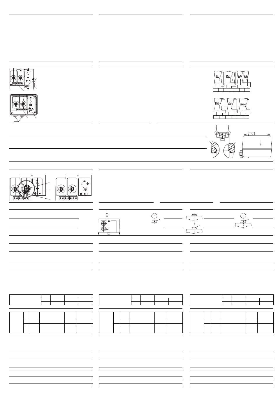
4.2 Elektrischer Anschluss
Electrical connection
Elektrické zapojení
(A)
(B)
- Das Gerät entspricht der Schutzklasse I
- Anschlussverbindung geeignet für fest verlegte
Leitungen.
- Leitungseinführung erfolgt
ohne Zugentlastung.
Kabeleinführung:
2 Steckstutzen serienmäßig
2 Würgenippel M20x1,5
bei Typenzusatz /SW, Dichtbereich 8-10 mm
- Anschlussleitung
(Leitungsdurchmesser 5 bis 10 mm)
durch die Verschraubung ( 2 ) führen.
Anbringungsart "X"
(ohne besondere Zurichtung), Schraub-
anschluss bis 2,5 mm
2
Leitungsquerschnitt.
- Anschluss entsprechend dem im Gehäusedec-
kel angebrachten Anschlussbild an Klemmen
( 3 ) durchführen.
- Schutzleiter an Klemme "PE" ( 1 )
anschließen.
- The instrument meets Protection class I
- The connection is suitable for fixed wiring.
- Cable entry without strain relief.
Cable entry:
2 push sockets as standard
2 clamping nipples M20x1.5
with extra code /SW, for 8-10 mm cable dia.
- Pass the connecting cable
(cable dia. 5 to 10 mm)
through the gland ( 2 ).
Attachment type "X"
(no special tools), screw connection up to
2.5 mm
2
conductor cross-section.
- Make the connection to the terminals ( 3 ) in
accordance with the connection diagram that
is affixed to the housing cover.
- Connect the protective conductor to the PE ter-
minal ( 1 ).
- Přístroj odpovídá ochranné třídě I
- Připojení je navrženo pro pevnou kabeláž.
- Pokládku vedení provádějte tak, aby nebylo
namáháno na tah.
Přivedení kabelu :
2 kabelové průchodky jako standard
2 záslepky M20x1,5
pro typ. doplněk /SW, těsnění 8-10 mm
- Připojovací vedení
(průměr vedení 5 až 10 mm) vést průchodkou
( 2 ).
Typ uspořádání “X” (bez zvláštního seřízení),
šroubovací spoj do 2,5 mm
2
průřezu vodiče.
- Připojení odpovídá podle nalepeného štítku na
termostatu na svorkách ( 3 ).
- Ochranný vodič připojit na svorku "PE" ( 1 ).
WTHc-2280 / WTHc-2280-SW
WTHc-2240/U / WTHc-2240-SW/U
( 1 ) TR (Ventilator
( 2 ) TW (Brenner)
( 3 ) STB (Bren-
ner)
( 1 ) TR (Fan)
( 2 ) TW (Burner)
( 3 ) STB (Burner)
( 1 ) TR (
ventilátor
)
( 2 ) TW (hořák)
( 3 ) STB (hořák)
4.3 Gehäuse schließen
Typenzusatz /SW
- Kunststoffdichtung
im Gehäuseunter-
teil ( 2 ) auf richti-
gen Sitz kontrollie-
ren.
- Gehäusedeckel ( 1 ) so positionieren, dass
sich die auf der Deckelinnenseite ange-
brachte Verstärkungsrippe ( 7 ) gegenü-
ber der am Gehäuseunterteil angebrach-
ten Zunge ( 6 ) befindet.
- Wiedereinschaltknopf ( 4 ) muss sich ge-
nau über dem innenliegenden Wieder-
einschaltknopf des Mikroschalters befin-
den, nur so kann der Wiedereinschalt-
knopf von außen betätigt werden.
- Gehäuseoberteil
( 1 ) auf das Ge-
häuseunterteil ( 2 )
setzen.
- Plombierbare
Zylinderschrauben
( 5 ) festdrehen.
Closing the housing
extra code /SW
- Make sure that the
plastic seal in the
housing bottom
( 2 ) is seated
correctly.
- Position the housing cover ( 1 ) in such a
way as to ensure that the reinforcing ridge
( 7 ) on the inside of the cover meets up
with the lip ( 6 ) on the housing bottom.
-The reset knob ( 4 ) must be located preci-
sely on top of the internal reset knob of
the microswitch, since this is the only
way the reset knob can be operated from
the outside.
- Place the housing
top ( 1 ) on the
bottom of the
housing( 2 ).
-Tighten the lead-
sealable cheese-
head screws ( 5 ).
Zavření krytu
typový doplněk /SW
- Zkontrolovat
správnou pozici
plastových těsnění
na spodní části kry-
tu (2).
- Kryt přístroje ( 1 ) přiložit tak, aby třecí plo-
chy krytu dosedly na zesílenou stranu
( 7 ) a na hrot ( 6 ) spodní části.
- Tlačítko pro opětovné zapnutí ( 4 ) se musí
nacházet přesně nad mikrospínačem pro
opětovné zapnutí, pouze tak může být spí-
nač z vnějšku spuštěn.
- Vrchní díl krytu ( 1 )
nasadit na spodní
díl přístroje ( 2 ).
- Plomobovatelné
cylindrické šrouby
zašroubovat ( 5 ).
5. Sollwert- /Grenzwerteinstellung
Setpoint /limit setting
Nastavení požadované / mezní hodn.
WTHc-2280
WTHc-2240/U
( 1 ) Sollwertsteller
( 2 ) Sollwertzeiger
( 3 ) Innenskala
- Gehäusedeckel abnehmen
und Sollwertsteller mit
Schraubendreher verstel-
len.
- Gehäusedeckel aufsetzen
und festschrauben.
( 1 ) Setpoint spindle
( 2 ) Setpoint marker
( 3 ) Internal scale
- Remove housing cover
and adjust setpoint spin-
dle using a screwdriver.
- Put housing cover back on
and tighten up the
screws.
( 1 ) Stavěcí člen
požadované
hodnoty
( 2 ) Zobrazení
požadované
hodnoty
( 3 ) Měřítko
- Odejmou kryt a stavěcí
člen pro pož. hodnotu
nastavit šroubovákem.
- Připevnit kryt a pevně
zašroubovat.
5.1 Entriegeln des STB
Resetting the STB
Reset STB
- Nach Unterschreiten des eingestellten Grenzwertes
(Gefahrentemperatur) um ca. 10K
kann der Sprungschalter entriegelt werden.
( A )
WTHc-2280 /
WTHc-2240/U
( B )
WTHc-2280-SW /
WTHc-2240/U/SW
1.
Hutmutter ( 1 )
abschrauben.
2.
Wiedereinschaltknopf ( 2 )
drücken, bis der Mikro-
schalter entriegelt ist.
3.
Hutmutter ( 1 )
aufschrauben.
- If the temperature falls below the set limit
(critical temperature) by about 10 °C,
the snap-action switch can be reset.
Unscrew
cap nut ( 1 ).
Press reset knob ( 2 )
until the microswitch is
reset.
Screw cap nut
( 1 ) back on.
- Po poklesu teploty o cca 10K od nastavené mezní hodnoty (ne-
bezpečné teploty)
může být pružinový spínač opět odblokován.
Kloboučkovou
matici odšrou-
bovat ( 1 ).
Appuyer sur le bouton de réar-
mement ( 2 ) jusqu’ŕ ce que le
microrupteur soit déverrouillé.
Kloboučkovou
matici našroubo-
vat ( 1 ).
6. Selbstüberwachung
Self-monitoring
Vlastní kontrola
Verhalten beim Bruch des Messsystems
Beim STB wird bei Messsystembruch (Undichtheit) der Stromkreis bleibend
geöffnet und der Mikroschalter zusätzlich verriegelt.
Response to a fracture of the measuring system
On the STB, a fracture of the measuring system (leakage) will cause the circuit to
open permanently and, in addition, the microswitch will be locked out.
Stav při přerušení měřicího systému
Pro typ STB se při přerušení měřicího systému (netěsnost) proudový obvod tr-
vale rozpojí a mikrospínač bude dodatečně zablokován.
Verhalten bei Untertemperatur
Wird beim STB die minimale Fühlertemperatur -20°C unterschritten, wird der
Stromkreis geöffnet. Bei Temperaturanstieg schließt sich der Stromkreis wieder
selbsttätig.
Response to low temperature
If, on the STB, the temperature at the probe falls below -20°C (minimum tempe-
rature), the circuit will also open. The circuit will close automatically when the
temperature rises.
Reakce na příliš nízkou teplotu
Pokud dojde u STB k poklesu teploty pod -20 °C, prodouvý obvod bude násled-
ně rozpojen.
Při zvýšení teploty se proudový obvod opět uzavře
.
7. Technische Daten
Technical data
Technická data
Wirkungsweise:
gemäß DIN EN 60730-1 und
DIN EN 60730-2-9
TR
1 BL
TW
2 BL
STW(STB)
2 BKLP
STB
2 BFKLP
Kurzzeichenerklärung:
1 Wirkungsweise Typ 1
2 Wirkungsweise Typ 2
B automatische Wirkungsweise
mit Mikroabschaltung
F nur mit Werkzeug rückstellbar
K mit Fühlerbruch-Sicherung
L keine Hilfsenergie erforderlich
P Wirkungsweise Typ 2,
durch deklarierte Temperaturwechsel geprüft
Mode of operation:
to EN 60730-1 and
EN 60730-2-9
TR
1 BL
TW
2 BL
STW(STB)
2 BKLP
STB
2 BFKLP
Explanation of code:
1 mode of operation type 1
2 mode of operation type 2
B automatic mode of operation,
with micro-disconnection
F can only be reset with tools
K probe fail-safe
L no auxiliary power required
P mode of operation type 2,
verified through declared temperature cycling
Typ funkce :
podle EN 60730-1
EN 60730-2-9
TR
1 BL
TW
2 BL
STW(STB)
2 BKLP
STB
2 BFKLP
Vysvětlení zkratky :
1 Funkce typ 1
2 Funkce typ 2
B Automatický účinek
s mikro-rozepnutím
F Může být resetován pouze pomocí nářadí
K S jištěním přerušení čidla
L Není nutná pomocná energie
P Účinek typ 2
zkoušeno
deklarovaným
střídáním teploty
zulässige Umgebungs-
temperatur im Gebrauch
Fernleitung
Schaltkopf
Permissible ambient
temperature in operation
Capillary
Switch head
Povolená teplota okolí
Kapilára
Spínací hlavice
max.
+80°C
+80°C
+80°C
max.
+80°C
+80°C
+80°C
max.
+80°C
+80°C
+80°C
min.
-40°C
-40°C
0°C
min.
-40°C
-40°C
0°C
min.
-40°C
-40°C
0°C
zulässige Fühlertemperatur:
max. Skalenendwert +15%
Permissible probe temperature:
max. end of scale +15%
Povolená teplota čidla :
max. hodnota měřítka +15%
zulässige Lagertemperatur:
max. 50°C, min. -50°C
Permissible storage temperature:max. 50°C, min. -50°C
Povolená teplota skladování :
max. 50°C, min. -50°C
Schalt-
punktge-
nauigkeit
Kurz-
zeichen
im oberen Drittel der
Skala bzw. am Grenzwert
am Skalen-
anfang
Schaltdifferenz
in K
Switching
point
accuracy
Code
in upper third of scale or at
limit
at start of
scale
Switching
differential
°C
Přesnost
spínacího
bodu
Zkratka
V horní třetině měřítka
resp. na mezní hodnotě
Na začátku
měřítka
Spínací dife-
rence v K
TR *
2
± 4K
± 6K
14 ± 2
TR *
2
± 4K
± 6K
14 ± 2
TR *
2
± 4K
± 6K
14 ± 2
TW *
2
± 4K
± 4K
0
6 ± 1
TW *
2
± 4K
± 4K
0
6 ± 1
TW *
2
± 4K
± 4K
0
6 ± 1
STB
80
40
+0 K
-5
- -
- -
STB
80
40
+0 K
-5
- -
- -
STB
80
40
+0 K
-5
- -
- -
* Fühlerkennzeichnung bei Ausführung der Fernleitung: Ventilatorregler TR: ROT, Brennerwächter TW: BLAU
* Probe coding on version with capillary: fan controller TR: RED, burner monitor TW: BLUE
* Značení čidla dle provedení: ventilační regulátor TR : ČERVENÁ, hlídač hořáků TW : MODRÁ
mittlerer Umgebungstemperatureinfluss:
in % vom Skalenumfang, bezogen auf den Grenzwert. Bei einer Abweichung der Umge-
bungstemperatur am Schaltkopfgehäuse und / oder der Fernleitung von der Kalibrier-
Umgebungstemperatur +22°C, entsteht eine Schaltpunktver-
schiebung.
Höhere Umgebungstemperatur = niedrigerer Schaltpunkt
Niedrigere Umgebungstemperatur = höherer Schaltpunktt
Mean ambient temperature effect
in % of scale span referred to the limit value. A deviation from the ambient temperature
at the switch head and / or the capillary from the +22°C calibration ambient temperature
will result in a shift of the switching point:
higher ambient temperature = lower switching point
lower ambient temperature = higher switching point
Střední vliv teploty okolí :
(v % z měřicího rozpětí, vztaženo na mezní hodnotu. Při odchýlení od okolní te-
ploty na hlavici přístroje a / nebo vedení kapiláry od kabrační teploty okolí
+22 °C, může dojít k posunutí spínacího bodu.
.
Vyšší teplota okolí = nižší bod sepnutí
Nižší teplota okolí = vyšší bod sepnutí
maximal zulässige Schaltleistung:
(ergänzende Angaben zum Typenschildaufdruck)
AC 230 V +10%, 10(2) A, cos
ϕ = 1(0,6), DC 230 V +10%, 0,25 A
Max. permissible contact rating
(supplementary to details on nameplate)
10(2) A, 230 V AC +10%, p.f. = 1(0.6), 0.25 A, 230 V DC +10%
Maximální povolený spínaný výkon :
(doplňující údaje na typovém štítku výrobku)
230 V AC +10%, 10(2) A, cos
ϕ = 1(0,6), 230 V DC +10%, 0,25 A
Kontaktsicherheit:
Zur Gewährleistung einer möglichst großen Schaltsicherheit empfehlen wir eine Min-
destbelastung von: AC/DC 24 V, 20 mA
Contact reliability
To ensure maximum switching reliability, we recommend a minimum loading of 24 V
AC/DC, 20 mA.
Spolehlivost kontaktu :
Pro zachování nejdelší možné spínací spolehlivosti doporučujeme nejmenší
zátěž: 24 V AC/DC, 20 mA
Bemessungs-Stoßspannung: 2500 V (über die schaltenden Kontakte 400 V)
Rated surge voltage: 2500 V (via the switching contacts: 400 V)
Jmenovité rázové napětí : 2500 V (přes spínací kontakty 400 V)
Überspannungskategorie II:
Erforderliche Absicherung, siehe maximaler Schaltstrom
Overvoltage category II:
for required fusing, see max. contact rating
Kategorie přepetí II :
pro případné jištění,viz maximální spínaný proud.
Betriebsmedium: Luft
Operating medium: air
Provozní médium : vzduch
Zeitkonstante t
0,632
: in Luft
≤ 120 s
Time constant t
0.632
: in air
≤ 120 sec
Časová konstanta t
0,632
: ve vzduchu
≤ 120 s
Schutzart: EN 60529-IP40, serienmäßig - EN 60529-IP54, bei Typenzusatz /SW
Enclosure protection: IP40 to EN 60529 (standard), IP54 to EN 60529 (with extra code /SW)
Ochranné krytí : EN 60529-IP40, sériově - EN 60529-IP54, u typ. doplňku /SW
1
2
3
4
5
6
°C
70
80
90
°C
80
20
40
60
70
50
30
( 1 )
( 2 )
( 3 )
70
80
90
°C°C
°C
80
20
40
60
70
50
30
1
2
3
4
5
6
( 2 )
( 3 )
( 1 )
1
2
3
4
5
6
1
4
2
1
4
2
II
I
4
2
4
7
1
( 1 )
( 2 )
( 3 )
1
2
3
4
5
6
1
4
2
( 1 )
1
4
2
2
1
( 2 )
( 3 )
( 6 )
( 7 )
( 4 )
( 5 )
( 1 )
( 2 )
°C
70
80
90
°C
80
20
40
60
70
50
30
1
2
3
4
5
6
TR
TW
STB
( 1 )
( 2 )
( 3 )
°C
70
80
90
°C
80
20
40
60
70
50
30
1
2
3
4
5
6
TR
TW
STB
7
( 1 )
( 2 )
( 1 )