Montage mounting montage, Einstellungen settings réglages – JUMO 604100 frostTHERM-AT/-DR Operating Manual User Manual
Page 2
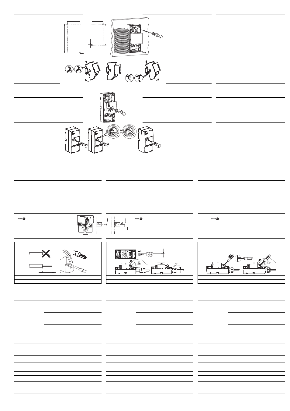
3. Montage
Mounting
Montage
3.3
Wandmontage
Bohrschablone
( 1 ) frostTHERM-AT
( 2 ) frost-THERM-DR
Wall mounting
Drilling jig
( 1 ) frostTHERM-AT
( 2 ) frost-THERM-DR
Montage mural
Gabarit
( 1 ) de perçage thermostat simple
( 2 ) de perçage Thermostat pour profilés chapeaux
3.4
Hutschiene
A Montage
B Demontage
Top hat rail
A Installation
B Disassembly
Profilé chapeau
A Montage
B Démontage
4. Einstellungen
Settings
Réglages
4.1
Sollwert- / Grenzwerteinstellung STW/STB
Setpoint / limit setting STW/STB
Réglage seuil/consigne STW/STB/
4.2
Entriegeln STB
Nach überschreiten des eingestelllten
Grenzwertes um ca. 3K kann der STB
entriegelt werden.
STB reset
The STB can be unlocked once the
set limit value is exceeded by approx.
3K.
Déverrouillage STB
Il est possible de déverrouiller le STB après dépassement
du seuil réglé d’env. 3K.
4.3
Verhalten bei Bruch des Messsystems
Bei Zerstörung des Messsystems, d.h. wenn das Medium entweicht, fällt
der Druck in der Membrane ab und öffnet beim STW und STB bleibend
den Stromkreis 1-2 und schließt den Stromkreis 1-4. Beim STB ist ein Ent-
riegeln nicht mehr möglich.
Response to measuring system fracture
If the measuring system is destroyed, i.e. if the medium escapes,
the pressure in the diaphragm drops and permanently opens current cir-
cuit 1-2 and closes current circuit 1-4 of the STW and STB.
It is no longer possible to unlock the STB.
Comportement en cas de rupture du système de mesure
En cas de destruction du système de mesure, c’est-à-dire si le fluide de
dilatation s’échappe, la pression sur la membrane chute et pour les exé-
cutions STW et STB le circuit 1-2 reste ouvert et le circuit 1-4 se ferme.
5. Installation
Electrical connection
Raccordement électrique
5.1
Vorschriften und Hinweise
■ Der elektrische Anschluss darf nur von Fachpersonal durchgeführt werden.
■ Bei der Wahl des Leitungsmaterials, bei der Installation und beim elektri-
schen Anschluss des Gerätes sind die Vorschriften der VDE 0100 "Bestim-
mungen über das Errichten von Starkstromanlagen mit Nennspannungen
unter 1000 V" bzw. die jeweiligen Landesvorschriften zu beachten.
■ Das Gerät völlig vom Netz trennen, wenn bei Arbeiten spannungs-
führende Teile berührt werden können.
■ Gerät an der Klemme PE mit dem Schutzleiter erden. Diese Leitung
sollte mindestens den gleichen Querschnitt wie die Versorgungsleitun-
gen aufweisen.
Regulations and notes
■ The electrical connection must only be made by qualified personnel.
■ The choice of cable, the installation and the electrical connection must
conform to the requirements of VDE 0100 “Regulations for the
installation of power circuits with nominal voltages below 1000 V”, or to
the appropriate local regulations.
■ If contact with live parts is possible while working on the unit, it must be
completely disconnected from the supply.
■ Earth the instrument at the PE terminal to the protective conductor. This
cable must have a cross-section that is at least as large as the supply
cables.
Prescriptions et remarques
■ Le raccordement électrique doit être effectué exclusivement par du per-
sonnel qualifié.
■ Aussi bien pour le choix du matériau des câbles, que pour l’installation
ou bien le raccordement électrique de l’appareil, il faut respecter la ré-
glementation en vigueur.
■ Débrancher les deux conducteurs du réseau lorsque des pièces sous
tension peuvent être touchées lors d’une intervention sur l’appareil.
■ Raccorder l’appareil à la terre sur la borne PE, avec le conducteur de
protection. Ce conducteur doit avoir la même section que les lignes
d’alimentation.
5.2
Elektrischer Anschluss
■ -Kontakt
(Steckklemme) * geeignet für An-
schlussquerschnitt 0,75...2,5mm
2
feindrähtig,
feindrähtig mit Aderendhülse eindrahtig.
■ Anschlussverbindung geeignet für fest verlegte Le-
itungen. Leitungseinführung mit Zugentlastung.
Anbringungsart X bzw. M.
■ Anschluss gemäß Anschlussbild durchführen.
STW
STB
Electrical connection
■
contact (plug-in terminal) * suitable for
conductor cross-section 0.75 — 2.5 mm
2
. Use
core-end ferrule with stranded conductor.
■ Connection suitable for fixed cabling. Cable entry
with strain relief. Attachment type X or M.
■ Implement the connection according to the wiring
diagram.
Raccordement électrique
■ Contact
(borne à fiche) * adapté à une section de fil 0,75 à
2,5mm
2
de faible diamètre, faible diamètre avec embout unifilaire.
■ Raccordement adapté à des câbles fixes. Entrée de câble avec dé-
charge de traction. Type de fixation X ou M.
■ Raccordement suivant schéma de raccordement.
*„Push-In
®
“-Klemmtechnik: patentierte Anschlusstechnik der Weidmüller GmbH & Co. KG, Detmold
*“Push-In
®
“ terminal technology is patented by Weidmüller GmbH & Co. KG, Detmold
*Technologie „Push-In®“ : connexion à insertion brevetée par Weidmüller GmbH & Co. KG, Detmold
1. Leitungen vorbereiten ( 1 ) geeignetes Crimpwerkzeug verwenden
2. Anschluss herstellen
3. Anschluss lösen
1. Prepare the cables
( 1 ) Use a suitable crimpng tool
2. Make the connection
3. Disconnection
1. Préparation des câbles
( 1 ) Utiliser l’outil de sertissage adapté
2. Brancher
3. Débrancher
6. Technische Daten
Technical data
Caractéristiques techniques
Elektrischer Kontakt
Sprungschalter mit einpoligem Umschaltkontakt
Electric contact
Snap switch with single-pole change-over con-
tact
Contact électrique
Contact à rupturer brusque avec contact
inverseur unipolaire
Schaltleistung
STW / STB
Am Öffnungskontakt
(Kontaktbahn 1-2)
AC 230 V +10%,
16 (2,5) A,
cos
= 1 (0,6)
DC 230 V +10%, 0,25 A
Contact rating
STW / STB
On the N/C contact
(contact deck 1-2)
AC 230 V +10%,
16 (2.5) A,
cos
= 1 (0.6)
DC 230 V +10%, 0.25 A
Pouvoir de coupure
STW / STB
Sur contact
à ouverture
(contacts principaux
1-2)
AC 230 V +10%,
16 (2,5) A,
cos
= 1 (0,6)
DC 230 V +10%, 0,25 A
STW
Am Schließkontakt
(Kontaktbahn 1-4)
AC 230 V +10%,
6,3 (2,5) A,
cos
= 1(0,6)
DC 230 V +10%, 0,25 A
STW
On the N/O contact
(contact deck 1-4)
AC 230 V +10%,
6.3 (2.5) A,
cos
= 1(0.6)
DC 230 V +10%, 0.25 A
STW
Sur contact
à fermeture
(contacts principaux
1-4)
AC 230 V +10%,
6,3 (2,5) A,
cos
= 1(0,6)
DC 230 V +10%, 0,25 A
STB
Am Signalkontakt
(Kontaktbahn 1-4)
AC 230 V +10%,
2 (0,4) A,
cos
= 1(0,6)
DC 230 V +10%, 0,25 A
STB
On the signal contact
(contact deck 1-4)
AC 230 V +10%,
2 (0.4) A,
cos
= 1(0.6)
DC 230 V +10%, 0.25 A
STB
Sur contact de
signalisation
(contacts principaux
1-4)
AC 230 V +10%,
2 (0,4) A,
cos
= 1(0,6)
DC 230 V +10%, 0,25 A
Anschlussquerschnitt
0,75...2,5mm
2
feindrähtig (eindrähtig, feindräh-
tig mit Aderendhülse)
Connection
cross section
0.75 to 2.5 mm
2
fine wired (single-wire, fine
wired with ferrule)
Section de fil
0,75 à 2,5mm
2
multibrin (unifilaire, multibrin
avec embout)
Schaltsicherheit
Zur Gewährung einer möglichst großen Schalt-
sicherheit empfehlen wir eine Mindestbelastung
von:
AC/DC = 24 V, 100mA bei Silberkontakten
Switching reliability
To ensure high switching reliability, we recom-
mend a minimum load of:
AC / DC = 24 V, 100 mA with silver contacts
Sécurité de coupure
Pour garantir la plus grande sécurité de coupure
possible, nous vous recommandons une charge
minimale de :
AC/DC = 24 V, 100mA avec contacts argentés
Schaltdifferenz
1.5 +/- 1K
Hysteresis
1,5 +/- 1K
Différentiel de coupure
1,5 +/- 1K
Schutzart
siehe Typenschild
Protection class
see nameplate
Indice de protection
voir plaque signalétique
Sollwerteinstellung
STW, STB
Schaltpunkt nach Abnahme des Gehäusedeckels
mit Schraubendreher einstellbar, Kontrolle des
eingestellten Schaltpunktes durch Sichtscheibe.
Set point adjustment
STW, STB
The switching point can be adjusted by means of a
screwdriver once the case lid has been removed, check
the set switching point through the inspection glass.
Réglage de la consigne
STW, STB
Point de commutation réglable après retrait du
couvercle du boîtier à l’aide d’un tournevis, contrô-
le du point de commutation réglé par transparent.
Fühlerleitungs-Ø
ca. 2,4 mm (oder 9,5 mm mit 1,8 m Kapillare)
Probe line-Ø
approx. 2.4 mm (or 9.5 mm with 1.8 m capillary tube)
Ø du câble de la sonde env. 2,4 mm (ou 9,5 mm avec 1,8 m capillaire)
zulässige maximale
Fühlertemperatur
120°C
maximum admissible
probe temperature
120°C
Température max. ad-
missible sur la sonde
120°C
zulässige Umge-
bungsbedingungen
auf Schaltkopf
und Fühlerleitung
-20°C ...+80°C
admissible ambient
conditions
on the switch head
and the probe line
-20°C ...+80°C
Conditions ambiantes
admissibles
Sur le boîtier et
sur le câble de la sonde
-20°C à +80°C
zul. Lagertemperatur
max. +80°C, min. -30°C
admissible storage
temperature
max. +80°C, min. -30°C
Température de
stockage admissible
max. +80°C, min. -30°C
Gewicht
ca. 0,2 kg
Weight
approx. 0.2 kg
Poids
env. 0,2 kg
94
42
Ш
4,5
( 1 )
Ш
4,5
37
76
( 2 )
1.
2.
A
1.
2.
B
2
4
1
1
4
2
1
4
2
( 1 )
11-13mm
24
Ø 6-12 mm
max. 3 mm