Montage installation montage, Installation installation raccordement électrique, Fühlermontage – JUMO 602031 Panel-Mounted Thermostat, heatTHERM Operating Manual User Manual
Page 2: Probe installation, Montage de la sonde, Elektrischer anschluss, Electrical connection, Raccordement électrique, Plug connection, Cosse de raccordement
3. Montage
Installation
Montage
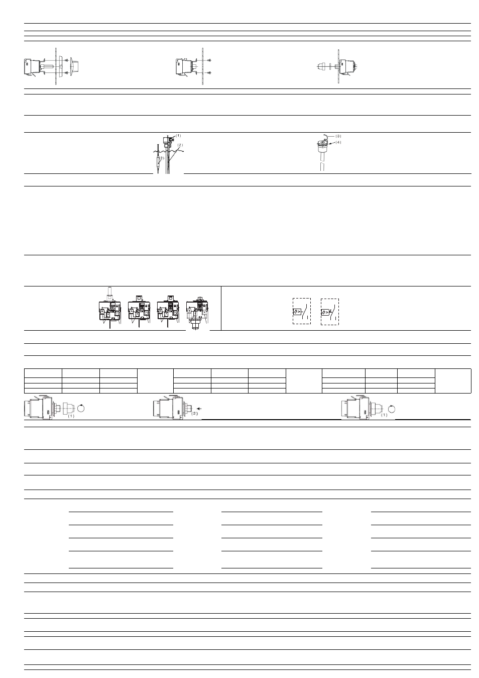
3.3 Einbau-Thermostat JUMO heatTHERM befestigen
Fastening the JUMO heatTHERM thermostat
Fixation du thermostat à encastrer JUMO heatTHERM
Gebrauchslage: beliebig
Operating position: any
Position d’utilisation : au choix
H
Kapitel „Abmessungen“ beachten !
Please note “Dimensions” chapter!
Tenir compte du chapitre „Dimensions“ !
TR
TR / TW / STW:
Mit 2 Befestigungsschrauben M4 (Abstand 28 mm) in die
Gewindebohrungen der Befestigungsbrücke.
STB:
1. Befestigungsbohrung Ø 10,5 mm in die Schalttafel bohren
2. Schutzkappe M 10 x 1, SW 10 abschrauben.
3. Befestigungsmutter M 10 x 1, SW13 abschrauben.
4. Thermostat in die Schalttafel einsetzen und mit Befes-
tigungsmutter befestigen. Kunststoffgewinde nicht über-
lasten! (max. 1Nm)
5. Schutzkappe aufschrauben.
TW / STW
TR / TW / STW:
With 2 fastening screws M4 (distance 28 mm) in the threaded
holes of the fastening bridge.
STB:
1. Drill a fastening hole Ø 10.5 mm in the control panel
2. Unscrew the protective cap M 10 x 1, SW 10.
3. Unscrew the fastening nut M 10 x 1, SW13.
4. Insert the thermostat in the control panel and fasten with a
fastening nut. Do not overload the plastic thread! (max. 1 Nm)
5. Screw on the protective cap.
STB
TR / TW / STW:
Avec 2 vis de fixation M4 (écart 28 mm) dans les trous taraudés des
ponts de fixation
STB:
1. Percer les trous de fixation Ø 10,5 mm dans la découpe du tableau
2.
Dévisser le cache M 10 x 1, OC 10.
3.
Dévisser l’écrou de fixation M 10 x 1, OC 13.
4.
Placer le thermostat dans la découpe du tableau et le fixer avec
l’écrou de fixation. Ne pas forcer le filetage en matière synthétique !
(max. 1Nm)
5.
Revisser le cache.
Fernleitung / Temperaturfühler / Schutzrohr
Capillary / temperature probe / protection tube
Capillaire / Sonde de température / Gaine de protection
A
Durchtrennen oder Knicken der Fernleitung des Einbau-Thermostaten JUMO heatTHERM
führt zum dauerhaften Ausfall des Gerätes!
Minimal zulässiger Biegeradius der Fernleitung ist 5 mm.
Erfolgt der Einbau des Temperaturfühlers in eine Schutzrohr, sind passende Schutzrohre zu
verwenden.
Cutting through or kinking the capillary of the JUMO heatTHERM panel-mounted
thermostat will result in permanent device failure!
The minimum permissible bending radius of the capillary is 5 mm.
If the temperature probe is to be installed in a protection tube, only use suitable protec-
tion tubes.
Le sectionnement ou le flambage du thermostat à encastrer JUMO heatTHERM provoque une
panne permanente de l’appareil !
Rayon de courbure min. autorisé : 5 mm.
Lorsque la sonde de température est montée dans une gaine de protection, veillez à utiliser les
gaines de protection adaptées
H
Mehrfachbelegung von Schutzrohren sind nur mit 2 oder 3 Rundfühlern mit Ø 6 mm und
Schutzrohren von 15 x 0,75 mm zulässig. Bei Belegung mit 2 Fühlern muß die werkseitig
mitgelieferte Andrückfeder in das Schutzrohr eingebaut sein. Im Betriebsmedium Luft muss
die Anschlussart 10 (ohne Schutzrohr) gewählt werden.
Fitting several probes into a common protection tube is only permitted with 2 or 3 plain
cylindrical probes 6 mm dia. and protection tubes 15 x 0.75 mm. When fitting 2 probes
into a common pocket, the factory-supplied spring clip must be fitted in the protection
tube. When used in air, probe mounting 10 (without protection tube) must be chosen.
Les regroupements de tubes de protection ne sont autorisés qu’avec 2 ou 3 sondes lisses de Ø
6 mm et tubes de protection 15 x 0,75 mm Pour un regroupement de 2 sondes il faut monter dans
le tube de protecion le ressort de pression livré avec le matériel. Dans le milieu de fonctionnement
Air il faut sélectionner le type de raccordement 10 (sans tube protecteur).
H
Fühlermontage
■ Der Temperaturfühler ( 2 ) muss vollständig in das Medium eingetaucht sein,
da sonst größere Schaltpunktabweichungen auftreten
■ Bei den Anschlussarten 20, 23 und 24 wird der Temperaturfühler mit dem
Klemmstück ( 1 ) in das Schutzrohr arretiert.
■ Biegeradius ( 3 ) ≥ 5 mm.
■ Bei Anschlussart 28/29/49, Fühler mit Klammer ( 4 ) gegen Herausgleiten si-
chern.
Probe installation
■ The temperature probe ( 2 ) must be completely immersed in the medium,
since otherwise there will be appreciable deviations from the switching point.
■ For connection types 20, 23, and 24, the temperature probe is fixed in the
protection tube with the clamping piece ( 1 ).
■ Bending radius ( 3 ) ≥ 5 mm.
■ With connection 28/29/49 the probe must be protected against sliding with
clamp ( 4 ).
Montage de la sonde
■ La sonde de température ( 2 ) doit être entièrement immergée dans le milieu
de mesure pour éviter des variations trop importantes du point de contact
■ En présence de types de raccordement 20, 23 et 24 le capteur de tempéra-
ture est arrêté par l'élément de serrage ( 1 ) dans le gaine de protecton.
■ Rayon de courbure ( 3 ) ≥ 5 mm.
■ Avec doigt de gant 28/29/49, prévoir le clip de blocage ( 4 ) du capillaire.
4. Installation
Installation
Raccordement électrique
V
Vorschriften und Hinweise
■ Der elektrische Anschluss darf nur von Fachpersonal durchgeführt werden.
■ Bei der Wahl des Leitungsmaterials, bei der Installation und beim elektrischen Anschluss
des Gerätes sind die Vorschriften der VDE 0100 "Bestimmungen über das Errichten von
Starkstromanlagen mit Nennspannungen unter 1000 V" bzw. die jeweiligen Landesvors-
chriften zu beachten.
■ Das Gerät völlig vom Netz trennen, wenn bei Arbeiten spannungsführende Teile berührt
werden können.
■ Gerät an der Klemme PE mit dem Schutzleiter erden. Diese Leitung sollte mindestens
den gleichen Querschnitt wie die Versorgungsleitungen aufweisen. Erdungsleitungen ster-
nförmig zu einem gemeinsamen Erdungspunkt führen, der mit dem Schutzleiter der Span-
nungsversorgung verbunden ist. Erdungsleitungen nicht durchschleifen, d.h. nicht von ei-
nem Gerät zum anderen führen.
■ Neben einer fehlerhaften Installation können auch falsch eingestellte Werte am Thermostat
den nachfolgenden Prozess in seiner ordnungsgemäßen Funktion beeinträchtigen oder zu
sonstigen Schäden führen. Die Einstellung sollte nur dem Fachpersonal möglich sein. Bitte
in diesem Zusammenhang die entsprechenden Sicherheitsvorschriften beachten.
Regulations and notes
■ The electrical connection must only be made by qualified personnel.
■ The choice of cable, the installation and the electrical connection must conform to the re-
quirements of VDE 0100 “Regulations for the installation of power
circuits with nominal voltages below 1000 V”, or to the appropriate local
regulations.
■ If contact with live parts is possible while working on the unit, it must be
completely disconnected from the supply.
■ Earth the instrument at the PE terminal to the protective conductor. This cable must have
a cross-section that is at least as large as the supply cables. Earth cables must be run in
a star configuration to a common earth point which is connected to the protective earth
conductor of the supply. Do not loop earth cables, i.e. do not run them from one instru-
ment to another.
■ Apart from faulty installation, incorrect settings on the thermostat may also
impair the proper functioning of the subsequent process or lead to damage. Setting up
must therefore be restricted to qualified personnel.
Please observe the corresponding safety regulations in this respect.
Prescriptions et remarques
■ Le raccordement électrique ne doit être effectué que par du personnel qualifié
■ Il faut respecter la réglementation VDE 0100 en vigueur "Prescriptions à propos des ins-
tallations à courant fort avec tensions nominales 1000 V" aussi bien pour le choix du ma-
tériau des câbles que pour l’installation ou le raccordement électrique.
■ Débrancher l’appareil, lorsque des pièces sous tension peuvent être touchées lors d’une
intervention sur l’appareil.
■ Raccorder l’appareil à la terre sur la borne PE avec le conducteur de protection. Ce
conducteur doit avoir la même section que les lignes d’alimentation. Amener les lignes de
mise à la terre en étoile à un point de terre commun relié à la tension d’alimentation par le
conducteur de protection. Ne pas boucler les lignes de mise à la terre, c.-à-d. de pas les
amener d’un appareil à l’autre.
■ Outre une installation défectueuse, des valeurs mal réglées sur le thermostat peuvent al-
térer le bon fonctionnement du process ou provoquer des dégâts. Le réglage ne devrait
être effectué que par du personnel qualifié et compétent Nous vous prions donc de res-
pecter les règles de sécurité correspondantes
Elektrischer Anschluss
■ Klemmen und Anschlüsse geeignet für innere Leiter
■ Anschlussverbindung geeignet für fest verlegte Leitung
■ Leitungsführung ohne Zugentlastung
■ Schutzklasse I, einbezogen sind:
- Schaltkopf inklusiv 4000 mm Cu-Kapillare (einschließlich Fühlerlänge)
- Nur der Schaltkopf bei CrNi-Kapillare
Electrical connection
■ Terminals and connections are suitable for internal conductors.
■ The connections are suitable for fixed cables.
■ Cable entry without strain relief.
■ Protection class I, comprising:
- Switch head including 4000 mm Cu capillary (including probe length)
- Switch head only with CrNi capillary
Raccordement électrique
■ Bornes et raccordements adaptés aux conducteurs internes
■ Raccord adapté à un câble fixe
■ Le câblage est réalisé sans anti-traction
■ Dans la classe de protection I entrent :
- boîtier plus capillaire en cuivre 4000 mm (y compris longueur de sonde)
- uniquement le boîtier avec capillaire en CrNi
Anschlussstecker
( 1 ) Flachstecker,
A 6,3x0,8 DIN 46244
Plug connection
( 1 ) Cosse plate,
A 6,3x0,8 DIN 46244
Cosse de raccordement
( 1 ) Tab connector,
A 6,3x0,8 DIN 46244
Anschlussbild
Leitung kann ohne Sonderwerkzeug
angebracht oder ersetzt werden, unter
Verwendung von genormten Leitun-
gen ohne besondere Zurichtung (An-
bringungsart "X").
TR/ TW / STW
STB
Connection diagram
The cable can be fitted or replaced wi-
thout any special tools, using standar-
dized cables without any special pre-
paration (attachment type “X”).
Schéma de
raccordement
Il est possible de monter ou de rem-
placer le câble sans outils spéciaux,
en utilisant des câbles normalisés
sans préparation particulière (type
d’attache "X").
V
Bei Fühlern, Kapillarleitungsarten und Kapillarleitungslängen, die nicht in die Schutzklasse I
einbezogen sind, muss der Anwender für den erforderlichen Schutz gegen elektrischen
Schlag sorgen.
In the case of probes, capillary types/lengths that are not covered by Protection class I, the
user must take the necessary protective measures against electric shock.
Pour les sondes, les types et longueurs de capillaire qui n’entrent pas dans la classe de
protection I, l’utilisateur doit prendre les mesure de protection nécessaires contre les chocs
électriques.
5. Sicherheitsfunktionen des STB / STW
Safety functions of the STB / STW
Fonctions de sécurité du STB / STW
H
Entriegeln des STB: Nach Unterschreiten des eingestellten Grenzwertes (Gefahrentempe-
ratur) um den in der Tabelle angegebenen Werte kann der Sprungschalter entriegelt werden.
Unlocking the STB: once the temperature falls below the selected limit value (and the tem-
perature is therefore dangerous) by the amount indicated in the table then the snap-action
switch can be unlocked .
Déverrouillage du STB : le contact à rupture brusque peut être déverrouillé lorsque la
temp. se situe en-dessous du seuil réglé (temp. dangereuse) ; val.indiquées dans le tableau.
Messbereich °C
im oberen Drittel
am Skalenanfang
Andere Entriege-
lungsdifferenzen
auf Anfrage.
Measuring range °C
In the upper third
At the scale begin-
ning
Other unlocking
differences upon
inquiry.
Etendue de mesure °C
dans le tiers
supérieur
en début d’échelle
Autres différentiels
de déverouillage sur
demande.
95 ... 120, 70 ... 130
ca. 10K
ca. 10K
95 to 120, 70 to 130
Approx. 10K
Approx. 10K
95 а 120, 70 а 130
env. 10K
env. 10K
20 ... 150
ca. 15K
ca. 30K
20 to 150
Approx. 15K
Approx. 30K
20 à 150
env. 15K
env. 30K
50 ... 300
ca. 25K
ca. 45K
50 to 300
Approx. 25K
Approx. 45K
50 à 300
env. 25K
env. 45K
H
h Schutzkappe ( 1 ) abschrauben.
h Unscrew the protection cap ( 1 ).
h Dévisser le cache ( 1 ).
h Wiedereinschaltknopf ( 2 ) drücken, bis Sprungschalter entriegelt ist.
h Press the reset button ( 2 ) until the snap-action switch is reset.
h Appuyer sur le bouton de réarmement ( 2 ) jusqu’à ce que le contact à rupture
brusque soit déverrouillé
h Schutzkappe ( 1 ) aufschrauben.
h Screw the protection cap ( 1 ) back on.
h Revisser le cache ( 1 ).
5.1 Selbstüberwachung
(STB + STW)
Self-monitoring
Autosurveillance
H
Verhalten beim Bruch des Messsystems
STW, STB:
Bei Zerstörung des Messsystems, d.h. wenn die Ausdehnungsflüssigkeit
entweicht, fällt beim JUMO heatTHERM der Druck im Messsystem ab –
der Stromkreis 1-2 wird bleibend geöffnet.
STB:
Eine Entriegelung des STB ist nicht mehr möglich.
Response to a fracture of the measuring system
In the event of a fracture of the measuring system, i.e. if the expansion liquid leaks, the
pressure in the measuring system on the JUMO heatTHERM drops and the circuit 1-2 stays
open permanently. A reset is no longer possible.
Comportement en cas de rupture du système de mesure
En cas d’endommagement du système de mesure, c.-à-d. dans le lorsque le liquide d’ex-
pansion s’échappe, la pression du JUMO heatTHERM chute système de mesure – le circuit
électrique 1-2 reste ouvert. Un déverrouillage n’est plus possible.
H
Verhalten bei Untertemperatur (STB + STW)
Bei Temperaturen unter -20 °C öffnet sich der Stromkreis 1-2, schließt sich jedoch bei Tem-
peraturanstieg wieder selbsttätig.
Response to low temperature (STB)
If the temperature falls below -20 °C, then circuit 1-2 will open, but will close again automa-
tically when the temperature rises.
Comportement en cas de température trop basse (STB)
Avec des températures inférieures à -20 °C le circuit électrique 1-2 s’ouvre, mais se referme
automatiquement lorsque la température remonte.
6. Technische Daten
Technical data
Caractéristiques techniques
zulässige Umgebungs-
temperatur im Ge-
brauch
An Fernleitung
und Schaltkopf
max. +80 °C
Am Temperaturfühler
– max. Sollwert +25 K bzw. +15%
– bei Flüssigkeitsfüllung max. 400 °C
Permissible ambient
temperature in
operation
At capillary and
switch head
Max. +80 °C
At temperature probe
– Max. setpoint value +25 °C or +15 %
– For liquid filling max. 400 °C
Température ambiante
autorisée en service
Sur le capillaire et le
boîtier
max. +80°C
Sur la sonde de température
– Consigne max. +25 K et/ou +15%
– pour remplissage liquide 400 °C max.
zulässige
Lagertemperatur
max. +80 °C (wenn max. Sollwert+25K
≥ +80 °C; sonst max.
Sollwert +25K = max. Lagertemperatur), min. -50 °C
Permissible
storage temperature
Max. +80 °C (if max. set point value is +25K
≥ +80 °C; otherwise,
max. set point value +25K = max. storage temperature), min. -50 °C
Température
de stockage autorisée
max. +80 °C (si consigne max. +25K
≥ +80 °C; sinon consigne
max. +25K = température de stockage max.), min. -50 °C
maximale
Schaltleistung
Am Öffnungskontakt
(Kontaktbahn 1-2)
AC 400 V +10%, 16 A
AC 230 V +10%, 16 (2,5) A, cos
ϕ = 1 (0,6)
DC 230 V +10%, 0,25 A
Maximum
contact rating
Break (SPST-NC)
Contact (contacts 1-2)
16 A, AC 400 V +10%
16 (2.5) A, cos
ϕ = 1 (0.6), AC 230 V +10%
0.25 A, DC 230 V +10%
Pouvoir
de coupure maximal
Sur contact à ouver-
ture (contact 1-2)
AC 400 V +10%, 16 A
AC 230 V +10%, 16 (2,5) A, cos
ϕ = 1 (0,6)
DC 230 V +10%, 0,25 A
TR, TW, STW Am Schließkontakt
(Kontaktbahn 1-4)
AC 400 V +10%,6,3 A
AC 230 V +10%, 6,3 (2,5) A, cos
ϕ = 1(0,6)
DC 230 V +10%, 0,25 A
TR, TW, STW Make (SPST-NO)
Contact (contacts 1-4)
6.3 A, AC 400 V +10%
6.3 (2.5) A, cos
ϕ = 1(0.6), AC 230 V +10%
0.25 A, DC 230 V +10%
TR, TW, STW Sur contact à ferme-
ture (contact 1-4)
AC 400 V +10%,6,3 A
AC 230 V +10%, 6,3 (2,5) A, cos
ϕ = 1(0,6)
DC 230 V +10%, 0,25 A
STB Am Signalkontakt
(Kontaktbahn 1-4)
AC 400 V +10%, 2 A
AC 230 V +10%, 2(0,4) cos
ϕ = 1(0,6)
DC 230 V +10%, 0,25 A
STB At signal contact
(contact path 1-4)
2 A, AC 400 V +10%
2(0.4) cos
ϕ = 1(0.6), AC 230 V +10%
DC 230 V +10%, 0.25 A
STB Sur le contact
de signalisation
(contacts 1-4)
AC 400 V +10%, 2 A
AC 230 V +10%, 2(0,4) cos
ϕ = 1(0,6)
DC 230 V +10%, 0,25 A
Sprungschalter
mit Goldauflage
(Typenzusatz 702)
AC/DC 24 V, 0,1 A
Snap-action switch
gold-plated
(extra code 702)
0.1 A, 24 V AC/DC
Contact à rupture
brusque à revêtement
doré (option 702)
24 V AC/DC, 0,1 A
Zur Gewährleistung einer möglichst großen Schalt-
sicherheit empfehlen wir eine Mindestbelastung von:
– AC / DC = 24 V, 100 mA bei Silberkontakten
– AC / DC = 10 V, 5 mA bei vergoldeten Kontakten
To ensure the highest degree of switching reliability, we re-
commend a minimum loading of:
– AC / DC = 24 V, 100 mA for silver contacts
– AC / DC = 10 V, 5 mA for gold-plated contacts
Pour garantir la plus grande sécurité de coupure, nous vous
recommandons une charge minimale de :
– AC / DC = 24 V, 100 mA avec contacts argentés
– AC / DC = 10 V, 5 mA avec contacts dorés
Bemessungsstoßspannung: 2500 V
Rated surge voltage: 2500 V
Surtension transitoire assignée : 2500 V
erforderliche
Absicherung
siehe max. Schaltleistung
Required fusing
See max. contact rating
Fusible nécessaire
voir pouvoir de coupure max.
Schaltpunkt-
genauigkeit
bezogen auf den Grenzwert bei T
U
+22 °C =
siehe Typenschildangabe am Gerät
Switching point
accuracy
Referred to the limit value at T
A
+22 °C =
see details on nameplate affixed to instrument
Précision du point
de contact
par rapport au seuil à T
ambiante
+22 °C =
voir indications de la plaque signalétique sur l’appareil
mittlerer Umgebungs-
temperatureinfluss
bezogen auf den Sollw-
ert
Bei Abweichung der Umgebungstemperatur an Schaltkopf und
Fernleitung — von der Justierumgebungstemperatur +22 °C
entsteht eine Schaltpunktverschiebung von ca. -0,1
K
/
K
(gemessen bei Grenzwert +120 °C fest eingestellt und Fern-
leitungslänge 3000 mm)
Mean ambient
temperature effect
referred to setpoint
A deviation of the ambient temperature at the switch head and
capillary from the +22 °C calibration ambient temperature will
result in a shift of the switching point of about -0.1
°C
/
°C
(measured for the limit +120 °C, permanently set, and a ca-
pillary length of 3000 mm)
Influence moyenne de la
température ambiante par
rapport à la consigne
Si la température ambiante sur le boîtier et le capillaire est
différente de la température de caibrage +22 °C le point de
contact est déplacé de max. -0,1
K
/
K
(mesuré avec un seuil à +120 °C réglé fixe et longueur de ca-
pillaire 3000 mm)
Gewicht
ca. 0,12 kg
Weight
Approx. 0.12 kg
Poids
env. 0,12 kg
Schutzart
EN 60 529 - IP 00. Am eingebautem Gerät muss mindestens
die Schutzart EN 60529-IP40 vorhanden sein!
Verschmutzungsgrad 3
Enclosure protection
IP00 to EN 60 529. When installed, the device must be pro-
tected to at least IP40 to EN 60529.
Pollution degree 3
Indice de protection
EN 60 529 - IP 00. Indice de protection minimale requise
EN 60529-IP40 lorsque l’appareil est monté !
Degré de pollution 3
Betriebsmedium
Wasser, Öl, Luft, Heissdampf
Operating medium
Water, oil, air, superheated steam
Milieu de service
eau, huile, air, vapeur
Zeitkonstante t0,632
in Wasser
in Öl
in Luft / Heissdampf
≤ 45 s
≤ 60 s
≤ 120 s
Time constant t0.632
In water
In oil
In air/superhtd. steam
≤ 45 sec
≤ 60 sec
≤ 120 sec
Constante de temps
t0,632
dans l’eau
dans l’huile
dans l’air/ vapeur
≤ 45 s
≤ 60 s
≤ 120 s
Wirkungsweise
gemäß DIN EN 60 730-1, DIN EN 60 730-2-9 und DIN EN 14597
Mode of operation
According to EN 60 730-1, EN 60 730-2-9 and EN 14597
Fonctionnement
Suivant EN 60 730-1, EN 60 730-2-9 et EN 14597
STW: Typ 2BKLNP
STB: Typ 2BFHKLNPV
TR: Typ 2BL
TW: Typ 2BL
STW: Typ 2BKLNP
STB: Typ 2BFHKLNPV
TR: Typ 2BL
TW: Typ 2BL
STW: Typ 2BKLNP
STB: Typ 2BFHKLNPV
TR: Typ 2BL
TW: Typ 2BL
Anschlussleitung
Leitungsquerschnitt maximal 2,5 mm
2
Connecting cable
Conductor cross-section: max. 2.5 mm
2
Câble de raccordement
Section de fil maximale 2,5 mm
2
( 1 )
( 1 )
TR
( 1 )
( 1 )
TW
( 1 )
( 1 )
STW
( 1 )
( 1 )
STB
1
2 4
1
2 4