Derating tables – JUMO 709010 TYA-432 thyristor power switch Data Sheet User Manual
Page 2
01.08/00073739
Data Sheet 70.9010
M. K. JUCHHEIM GmbH & Co • 36035 Fulda, Germany
Page 2/3
General data
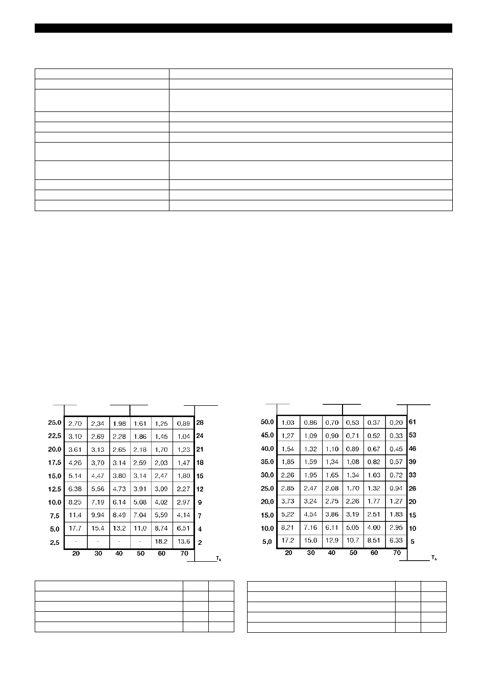
Derating tables
The maximum thermal resistance between the baseplate of the thyristor power switch and the environment R(
thSA
) is determined as a
function of the load currents and the different ambient temperatures. The matrix below has been provided for this purpose. The power
loss at a given nominal current can also be taken from this matrix.
Example:
Current I = 15A resistive load
T
A
= 40°C (measured during operation, with the power switch built into a switchgear cabinet)
Selected thyristor power switch: TYA 432-45/25, 265
The maximum thermal resistance of the heat sink can be seen from the matrix to be 3.8 °C/W.
Important note:
Use a silicone-based heat transfer compound between the heat sink and the thyristor power switch. If you use a heat transfer compound
that does not contain silicone, then you have to make sure that the chemical silicone substitute does not attack the Noryl SE 1 GFN 1
of the plastic housing. We recommend the use of silicone-based heat transfer compounds, e.g. Dow Corning.
To ensure safe operation at maximum performance, it is essential to strictly observe the thermal requirements according to the derating
tables.
TYA 432-45/25, 265
TYA 432-45/50, 530
Operating mode
zero-crossing switching
Electrical isolation
by optocoupler between control and power section; insulation voltage
≥
4kV
Thermal resistance
junction-case
0.8 °C/W for TYA 432-45/25, 265
0.5 °C/W for TYA 432-45/50, 530
Permissible ambient temperature
–20 to +70°C
Storage temperature
–40 to +100°C
Electrical connection
via screw terminals (load:
!
16mm
2
max. / control:
!
2.5mm
2
max.)
Electromagnetic compatibility
EN 61000 - 6 - 4
EN 61000 - 6 - 2
Electrical safety
overvoltage category III
pollution degree 3 (external)
Housing
Noryl 6FN 1
Enclosure protection
IP20
Weight
60g
Load current
[A]
Thermal resistance
[°C/W]
Power loss
[W]
Load current
[A]
Thermal resistance
[°C/W]
Power loss
[W]
Ambient temperature [°C]
Ambient temperature [°C]
,
Thermal resistance junction-environment, R
thja
< 20.0
°C/W
Thermal resistance junction-baseplate, R
thjc
< 0.80
°C/W
Thermal resistance baseplate-heat sink, R
thcs
< 0.20
°C/W
Max. permissible baseplate temperature
100
°C
Max. permissible junction temperature
125
°C
Thermal resistance junction-environment, R
thja
< 20.0
°C/W
Thermal resistance junction-baseplate, R
thjc
< 0.50
°C/W
Thermal resistance baseplate-heat sink, R
thcs
< 0.20
°C/W
Max. permissible baseplate temperature
100
°C
Max. permissible junction temperature
125
°C