Display and connection elements, Electrical isolation connection diagram – JUMO 705015 mTRON T - Relay Module 4-Ch. Data Sheet User Manual
Page 3
JUMO GmbH & Co. KG
Delivery address: Mackenrodtstraße 14
36039 Fulda, Germany
Postal address:
36035 Fulda, Germany
Phone:
+49 661 6003-0
Fax:
+49 661 6003-607
E-mail:
Internet:
www.jumo.net
JUMO Instrument Co. Ltd.
JUMO House
Temple Bank, Riverway
Harlow, Essex CM20 2DY, UK
Phone: +44 1279 635533
Fax:
+44 1279 635262
E-mail:
Internet: www.jumo.co.uk
JUMO Process Control, Inc.
6733 Myers Road
East Syracuse, NY 13057, USA
Phone: 315-437-5866
1-800-554-5866
Fax:
315-437-5860
E-mail:
Internet: www.jumousa.com
2013-05-07/00529108
Data Sheet 705015
Page 3/5
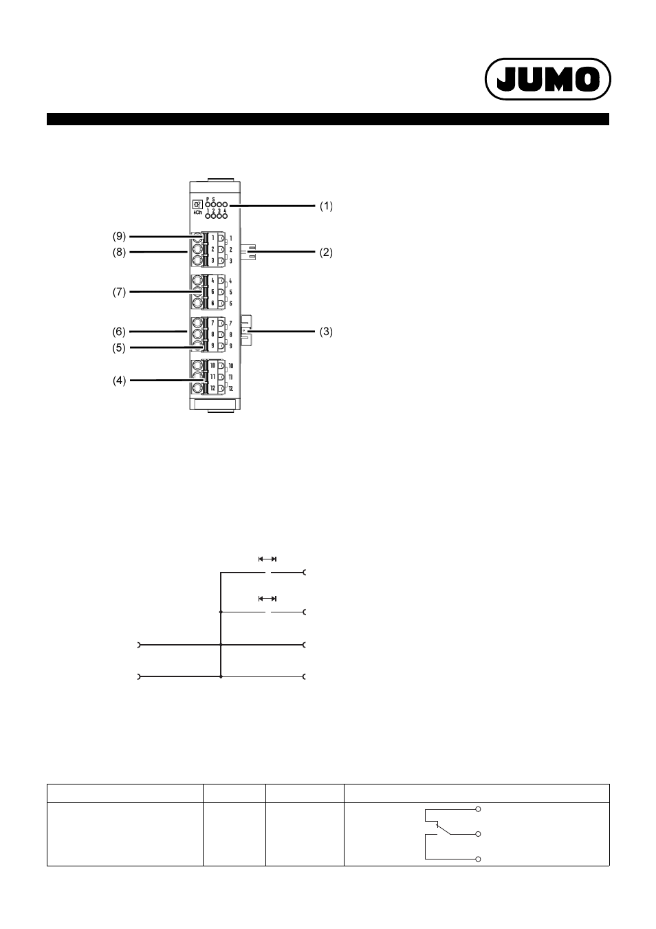
Display and connection elements
(1) Status displays (LED):
P = Voltage supply
S = Status
1 to 4 = Relay outputs
(LED is lit: Active)
(2) Voltage supply Out, DC 24 V
(3) Side system bus Out
(4) Relay output 4
(5) Relay output 3
(6) Side system bus In
(7) Relay output 2
(8) Voltage supply In, DC 24 V
(9) Relay output 1
Electrical isolation
Connection diagram
The connection diagram included in the data sheet provides initial information about the connec-
tion options. Only use the installation instructions or the operating manual for the electrical con-
nection. The know-how and the correct technical implementation of the safety warnings/
instructions contained in these documents are the prerequisite for the installation, electrical con-
nection, and initial start as well as for the safety during operation.
Connection
Output
Terminals
Symbol and terminal designation
Relay output (changeover contact)
1
2
3
4
1 to 3
4 to 6
7 to 9
10 to 12
1, 4, 7, 10
2, 5, 8, 11
3, 6, 9, 12
System bus
Voltage supply
DC 24 V
Relay output 1
AC 3800 V
»
Relay output 4
AC 3800 V
»
.
.
.
Voltage supply Out
Side system bus In
Side system bus Out
Voltage supply In