Connection diagram, Digital input, Digital outputs – JUMO 705030 mTRON T - Digital Input/Output Module Data Sheet User Manual
Page 5: External voltage supply
JUMO GmbH & Co. KG
Delivery address: Mackenrodtstraße 14
36039 Fulda, Germany
Postal address:
36035 Fulda, Germany
Phone:
+49 661 6003-0
Fax:
+49 661 6003-607
E-mail:
Internet:
www.jumo.net
JUMO Instrument Co. Ltd.
JUMO House
Temple Bank, Riverway
Harlow, Essex CM20 2DY, UK
Phone: +44 1279 635533
Fax:
+44 1279 635262
E-mail:
Internet: www.jumo.co.uk
JUMO Process Control, Inc.
6733 Myers Road
East Syracuse, NY 13057, USA
Phone: 315-437-5866
1-800-554-5866
Fax:
315-437-5860
E-mail:
Internet: www.jumousa.com
2013-07-09/00529111
Data Sheet 705030
Page 5/7
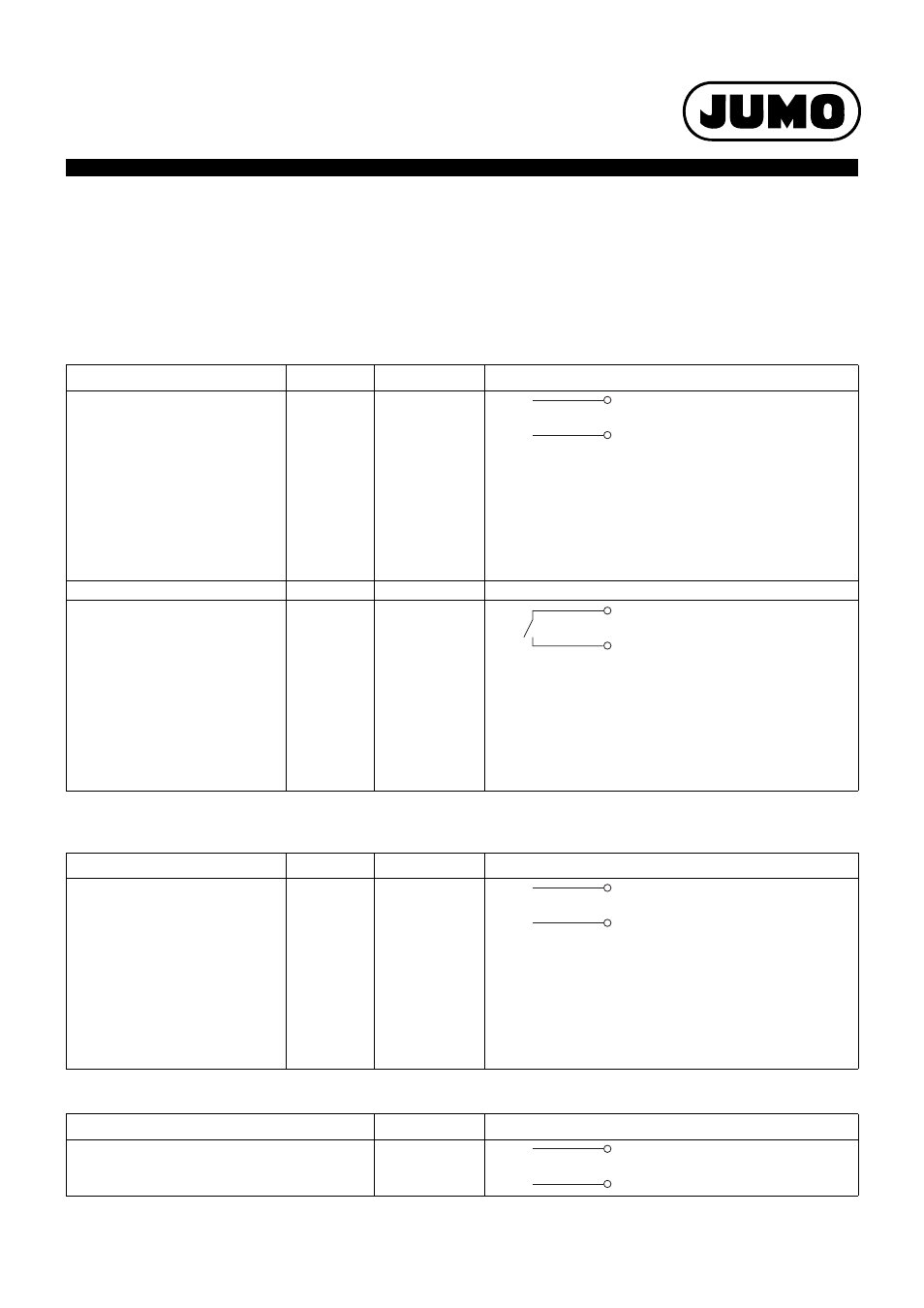
Connection diagram
The connection diagram included in the data sheet provides initial information about the connection options. Only use the installation instructions
or the operating manual for the electrical connection. The know-how and the correct technical implementation of the safety warnings/instructions
contained in these documents are the prerequisite for the installation, electrical connection, and initial start as well as for the safety during opera-
tion.
Digital input
The connection depends on the configuration (input or output).
Digital outputs
The connection depends on the configuration (input or output).
External voltage supply
Connection
Input
Terminals
Symbol and terminal designation
Apply signal DC 0/24 V to terminals
1 to 12
Ground reference via GND terminal
required!
1
2
3
4
5
6
7
8
9
10
11
12
1 and GND
2 and GND
3 and GND
4 and GND
5 and GND
6 and GND
7 and GND
8 and GND
9 and GND
10 and GND
11 and GND
12 and GND
1, 2, 3, 4, 5, 6, 7, 8, 9, 10, 11, 12
GND
Or:
Switch DC 24 V from terminal +24 V
to terminals 1 to 12 via floating con-
tact.
External voltage supply DC 24 V via
terminals +24 V and GND required!
1
2
3
4
5
6
7
8
9
10
11
12
1 and +24 V
2 and +24 V
3 and +24 V
4 and +24 V
5 and +24 V
6 and +24 V
7 and +24 V
8 and +24 V
9 and +24 V
10 and +24 V
11 and +24 V
12 and +24 V
+24 V
1, 2, 3, 4, 5, 6, 7, 8, 9, 10, 11, 12
Connection
Output
Terminals
Symbol and terminal designation
Output signal:
DC 0/24 V / maximum 500 mA
External voltage supply DC 24 V via
terminals +24 V and GND required!
1
2
3
4
5
6
7
8
9
10
11
12
1 and GND
2 and GND
3 and GND
4 and GND
5 and GND
6 and GND
7 and GND
8 and GND
9 and GND
10 and GND
11 and GND
12 and GND
1, 2, 3, 4, 5, 6, 7, 8, 9, 10, 11, 12
GND
Connection
Terminals
Symbol and terminal designation
DC 24 V
GND und +24 V
GND
+24 V
U
+
-
x
U
+
-
x
U
+
-
x