Dual dmx input and thru connectors, User interface, Dual dmx input and thru connectors user interface – Johnson Systems DPC-24-3000 Series Digital Pack Controller User Manual
Page 7
7
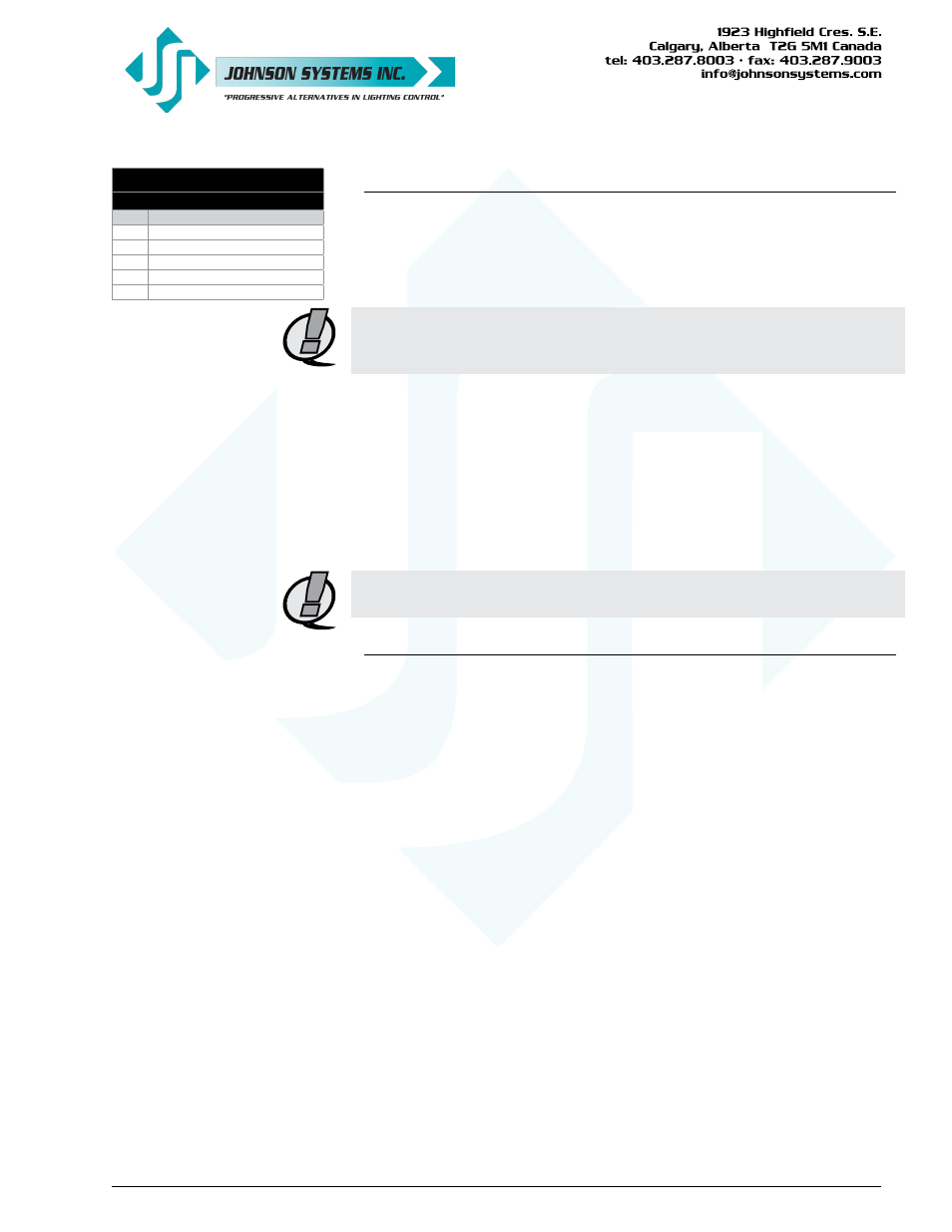
DMX Input and Thru
5-Pin XLR Connectors
PIN FUNCTION
1
DMX Shield / Common
2
DMX Data-
3
DMX Data+
4
Pass Thru Connection
5
Pass Thru Connection
Dual DMX Input and Thru Connectors
DPC-12 and DPC-24 control modules are equipped with dual (2) opto-
isolated DMX inputs. The DMX-A and DMX-B input and thru connectors (5-
pin XLR) are located on the front panel of the control module. A built-in DMX
protocol manager can be configured for various applications. Refer to menu
item “DMX MODE” on page 14 for further details.
NOTE: If DMX is connected internally, on a terminal block mounted inside
the CD80 dimmer pack, the DMX-B input is utilized, and the front
panel DMX-B input should not be used or data collision will occur.
• Complies with USITT DMX512-A (ANSI E1.11 - 2008), standard protocol
for digital data control.
• Recommended cable is Beldon 9829, 9842, Cat 5 or equivalent (low-
capacitance, twisted pair).
• Wiring must follow a daisy-chain topology.
• Maximum of 32 receiving devices on a single DMX line.
• Maximum cable length is 1,500 feet (455 meters).
• For more information, Google DMX, or visit:
NOTE: Ensure only the last (end-of-line) DMX receiving device is
terminated!
User Interface
DPC-12 and DPC-24 retrofit control modules are equipped with a user
interface. The user interface provides access to all programming and
configuration settings. System status is easily visible on the LCD display
and LED indicators. An infrared (I/R) LED allows for printout of all system
configuration settings when used with a hand held infrared printer (Johnson
System Inc., Part Number: JS-IP).
All of the programming is accomplished using four (4) switches. Within a few
minutes most users will find the menu structure very intuitive and easy to
navigate. All configuration settings are automatically stored in the on-board
EEPROM.