B&B Electronics Zlinx 485 User Manual
Page 29
Modbus Basics
Manual Documentation Number: Zlinx485m-1808
www.bb-elec.com
www.bb-europe.com
C
C
h
h
a
a
p
p
t
t
e
e
r
r
4
4
:
:
C
C
o
o
n
n
f
f
i
i
g
g
u
u
r
r
a
a
t
t
i
i
o
o
n
n
&
&
O
O
p
p
e
e
r
r
a
a
t
t
i
i
o
o
n
n
Zlinx 485 Manager software is used to configure Zlinx 485 hardware. Using Zlinx 485
Manager, the system can be configured to operate in Peer-to-Peer or Modbus modes
(receiving Modbus commands and data from a Modbus base module). Digital inputs can
be configured to operate in Discrete (on/off) or Frequency Counter modes and analog
inputs and outputs are configurable for voltage or current loop operation.
Configuring Zlinx 485
Zlinx 485 modules can be configured to operate as Modbus nodes or as serial links in
Peer-to-Peer mode.
Configuring Modbus Mode
When the Zlinx 485 receives a Modbus message to write to a discrete output (0xxxx
addresses in its memory map), the Zlinx 485 module turns on its corresponding digital
output. If a message containing holding register data is received (4xxxx addresses in its
memory map), the Zlinx 485 module converts the value to a voltage or current signal on
the corresponding analog output.
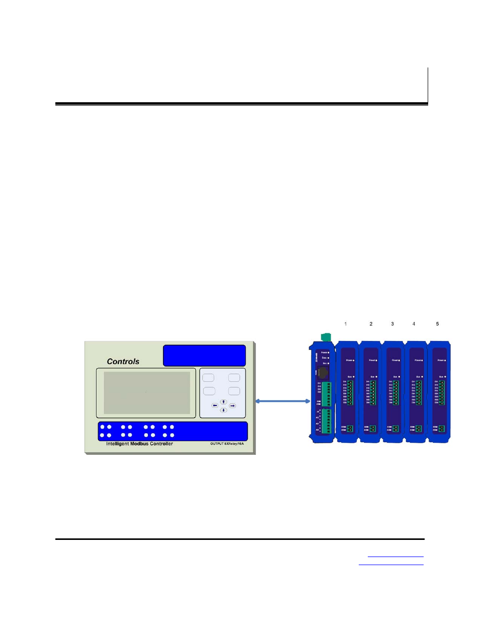
Figure 29.
Modbus Mode devices may be PLCs, RTUs, DCSs, or other Modbus devices,
with links up to 32 nodes per Modbus network
Figure 30.
Digital and analog signals applied to the Zlinx 485 Expansion module’s input terminals
are converted to Modbus messages to be sent back to the base module. Digital inputs are