Power supply connector – B&B Electronics Zlinx 485 User Manual
Page 10
Hardware
Manual Documentation Number: Zlinx485m-1808
www.bb-elec.com
www.bb-europe.com
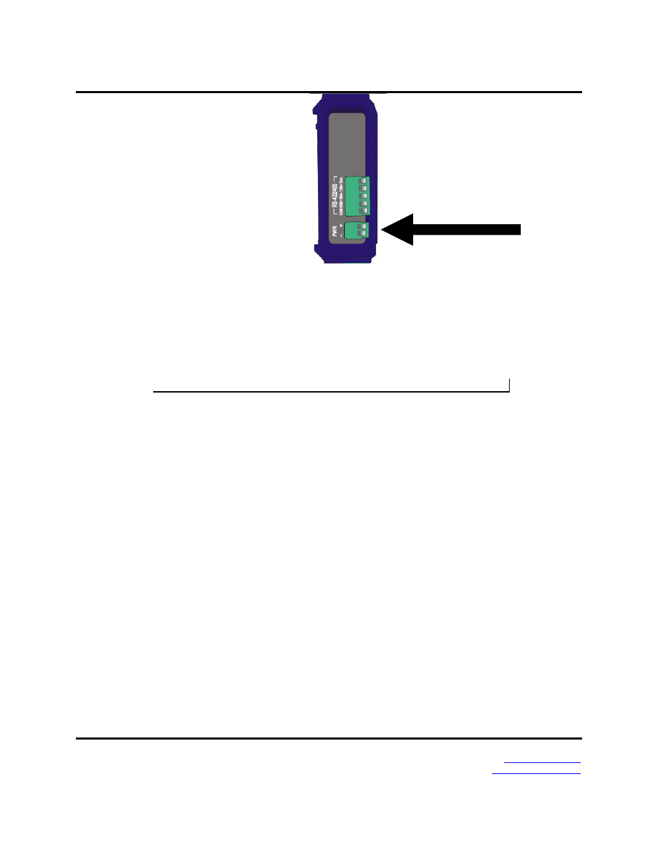
Figure 6.
Power Supply Connector
The Power Supply connector (base modules only) is a two-position removable terminal
block located on the top of the unit. Terminal spacing is 3.5 mm. The terminal block
accepts solid and stranded wires from 28 AWG to 16 AWG. Please check polarity
marking in Figure 8.
Refer to the following section for information on Power Supply Requirements.
Expansion modules receive power from the base module via the local bus connector.
Local Bus Connectors
Local Bus connectors are included on all base and expansion modules. These connectors
are dual row, 14 pin (2 mm spacing) connectors. Base modules have only a female
connector. Expansion modules have male connectors on one side and female connectors
on the other. Modules are plugged together to supply power and facilitate communication
between modules.
When adding an Expansion module to a Base module the male connector on the expansion
module plugs into the female connector on the base module. The second expansion module plugs
into the first, and so on, up to a maximum of six expansion modules.