INFICON BPG402-Sx ATM to Ultra-High Vacuum Gauge User Manual
Page 19
tina46e1-a (2010-03) BPG402.om
19
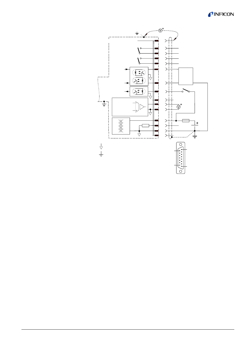
8
9
1
15
D-Sub,15 pins,
female,
soldering side
Filament status
SP
TxD
RxD
Degas
42 k
Ω
3
4
1
11
9
13
14
7
8
2
12
5
15
1.25 AT
24V
Degas
Ident.
RS232
10
-
-
-
1)
( )
Measuring
signal
-
V
S
6
Threshold value, SP
Common (power GND 24V supply)
Ground (housing, vacuum connection)
Electrical connection
Pin 1
Relay switching function, common contact
Pin 2
Measuring signal output
0 … +10 V
Pin 3
Threshold (setpoint)
1)
0 … +10 V
Pin 4
Relay switching function, n.o. contact
Pin 5
Supply common
0 V
Pin 6
Not connected internally
Pin 7
Degas (active high)
0 V/+24 V
Pin 8
Supply (V
s
) +24
V
Pin 9
Relay filament status, common contact
2)
Pin 10
Gauge identification
Pin 11
Relay filament status, n.o. contact
2)
Pin 12
Measuring signal common
Pin 13
RS232C, TxD
Pin 14
RS232C, RxD
Pin 15
Do not connect
1)
Do not connect pin 3 for normal operation of the gauge. This pin is reserved for
adjustment of the setpoint potentiometers (
→ 38).
2)
→ table on 28.
Sensor cable connection
BPG402-S, -SL
- TGF10 Tracer Gas Filler (36 pages)
- Sensistor ILS500 F Leak Detection Filler (90 pages)
- T-Guard Leak Detection Sensor (85 pages)
- T-Guard Leak Detection Sensor Interface description (40 pages)
- Sensistor ISH2000P Hydrogen Leak Detector, Panel Model (51 pages)
- Sensistor ISH2000 HySpeed Hydrogen Leak Detector (54 pages)
- LDS3000 Modular Leak Detector (52 pages)
- LDS3000 Modular Leak Detector Interface description (56 pages)
- BM1000 Bus module (14 pages)
- I/O1000 I/O module (18 pages)
- CU1000 Control unit (24 pages)
- Helium Leak Detector Modul1000 (130 pages)
- Helium Leak Detector Modul1000 Interface description (40 pages)
- UL5000 Dry Helium Leak Detector (108 pages)
- UL5000 Dry Helium Leak Detector Interface description (14 pages)
- UL1000 Fab Dry Helium Leak Detector (119 pages)
- HLD6000 Refrigerant Leak Detector (76 pages)
- HLD6000 Refrigerant Leak Detector Interface Description (40 pages)
- IO1000 I/O module (18 pages)
- Ecotec E3000 Multigas-Sniffer-Leak Detector (92 pages)
- Ecotec E3000 Multigas-Sniffer-Leak Detector Interface description (36 pages)
- Sensistor XRS9012 Hydrogen Leak Detector User Manual (28 pages)
- Sensistor XRS9012 Hydrogen Leak Detector Maintenance manual (14 pages)
- Extrima Ex-certified Hydrogen Leak Detector (62 pages)
- Sensistor ILS500 Leak Detection System (107 pages)
- Sensistor ISH2000 Hydrogen Leak Detector (58 pages)
- Sensistor ISH2000 Hydrogen Leak Detector (108 pages)
- Sensistor Sentrac Hydrogen Leak Detector (86 pages)
- Protec P3000(XL) Helium Leak Detector (132 pages)
- Pilot Plus Vacuum Gauge (2 pages)
- CO Check Carbon Monoxide Meter (2 pages)
- GAS-Mate Combustible Gas Leak Detector (12 pages)
- Whisper Ultrasonic Leak Detector (8 pages)
- Vortex AC Refrigerant Recovery Machine 115V (20 pages)
- Vortex AC Refrigerant Recovery Machine 230V (16 pages)
- Wey-TEK Refrigerant Charging Scale & Optional Charging Module (2 pages)
- Wey-TEK Refrigerant Charging Scale & Optional Charging Module (44 pages)
- D-TEK CO2 Refrigerant Leak Detector (12 pages)
- TEK-Mate Refrigerant Leak Detector (12 pages)
- Compass Refrigerant Leak Detector (12 pages)
- D-TEK Select Refrigerant Leak Detector (12 pages)
- Explorer Portable Gas Chromatograph (369 pages)
- MicroFID II Portable Flame Ionization Detector (89 pages)
- DataFID Portable Flame Ionization Detector for Landfill Emissions Monitoring (91 pages)
- Hydrostik Hydrogen Fuel Cylinder Installation (7 pages)