HYDAC HDA 5500-1-2-DC-000 User Manual
Page 15
HDA 5500 User Manual
- 15 -
Lo.1
Hi.1 plus 1%
Lo.1 minus 1%
P
t
Sicherheitszone
Sicherheitszone
Ein
Aus
Aus
Ein
Ein
Aus
Rückschaltwert
Schaltwert
Rückschaltwert
Schaltwert
Hi.1
The upper switch point and the lower switch point of a switching window can be individually
set for each switching output. The following setting ranges apply:
•
Upper switch point
1.0..99.5 % of the display range
•
Lower switch point
0.5..99 % of the display range
Important:
The switching window therefore only functions correctly (activation and deactivation of a
switching function), if all the switch points and switch-back points are larger than the lower
limit and smaller than the upper limit of the display range of a particular sensor.
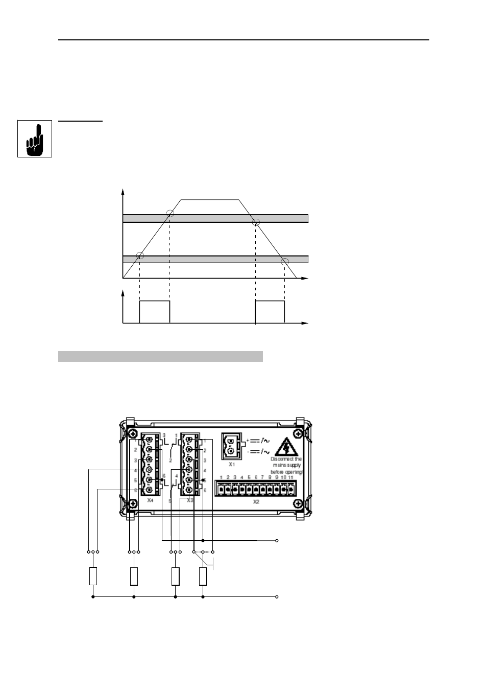
Example for switching output 1 (relay activated):
10.3 Connection of up to four switching outputs
Connection example for four switching outputs, e. g. HDA 5500-1-2-AC-000, is shown below.
Depending on the auxiliary voltage and load (especially for inductive loads) the external
circuit must be fitted with a varistor.
load 1
Aux. voltage
for load 1..4
SP1 N/C
SP2
SP2
load 2
SP1 N/O
SP3
SP3
load 3
SP4
SP4
load 4
Sicherheitszone = safety zone
Rückschaltwert = switch-back value
Schaltwert = switching value
Ein = on
Aus = off