Operating keys on the membrane keypad, Pin connection, Wiring diagram – HYDAC ETS 1700 User Manual
Page 2: 2 relay outputs, analogue output, supply voltage
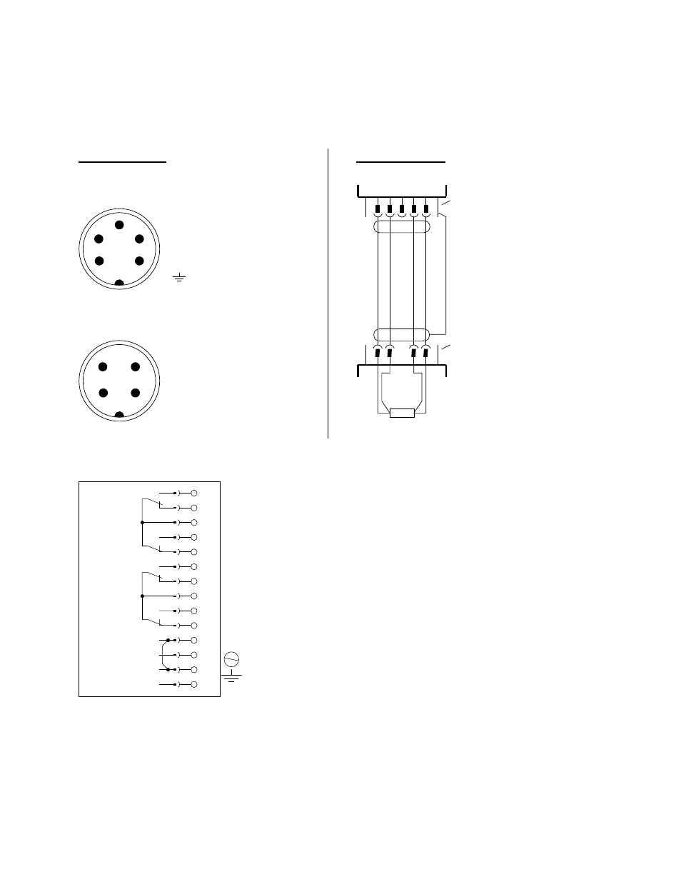
Pin connection
Internal view of pin connections (on the ETS 1700)
5-pole Binder connector, series 723
1
2
3
4
5
Pin 1
Pin 2
Pin 3
Pin 4
Pin 5
= + supply
= + signal
= reserved
= - signal
= - supply
= plug housi ng for
screen
Internal view of pi n connections (on the TFP 100)
4-pole Binder connector, series 714
1
2
3
4
Pin 1
Pin 2
Pin 3
Pin 4
= + supply
= + signal
= - signal
= - supply
Wiring diagram
TFP 100
Sensor
resistance
1 2 3 4 5
1 2
3 4
ETS 1700
5-pole
Binder connector,
series 723
4-pole Binder
connector, series
714
screened
connection li ne
3.2
Relay outputs, analogue output, supply voltage
1
2
3
4
5
6
7
8
9
10
11
12
13
14
Relay 4
= Switching point 4
Relay 3
= Switching point 3
Relay 2
= Switching point 2
Relay 1
= Switching point 1
Analogue output (0 V)
Analogue output (signal +)
Supply (0 V)
Supply (+ UB)
PE
4. Operating keys on the membrane keypad