Maintenance, Innovative fluid power, 2 inspection of components – HYDAC SB 600 User Manual
Page 3
INNOVATIVE FLUID POWER
25
PN#02073469 / 07.14 / ACU1102-1326
Maintenance
F
E
D
C
B
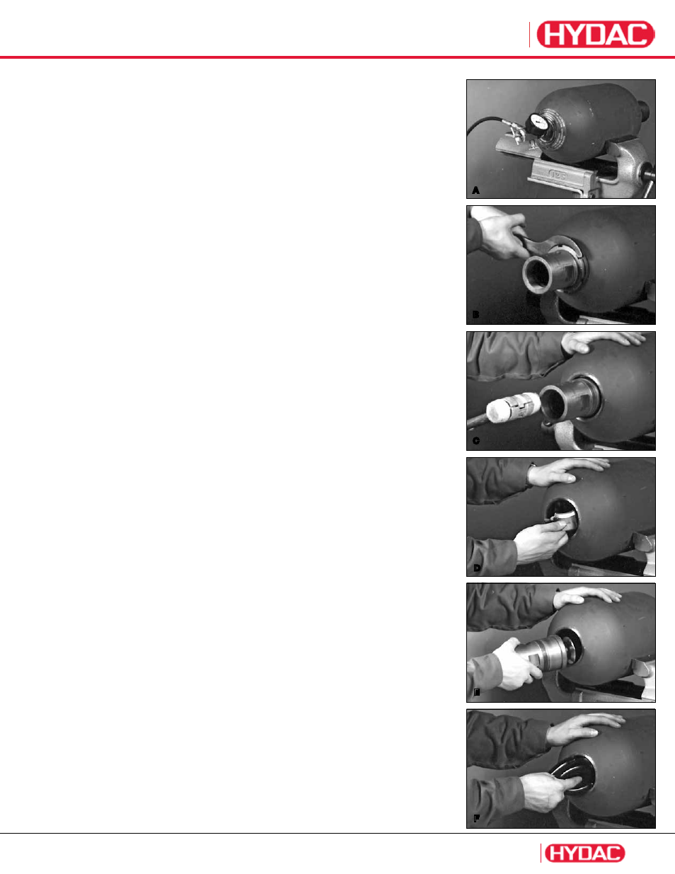
3. Bottom Repairable Bladder Accumulators
3.1 Disassembly
A After removal from the system, place the accumulator in a vice or secure it to a workbench.
Remove
valve protection cap
(item 6)
and unscrew
valve seal cap
(item 5)
. Attach the
proper HYDAC Charging and Gauging Unit and completely relieve the gas precharge
(refer to HYDAC Charging and Gauging brochure #02068202)
.
Remove
gas valve core
(item 3)
by using the gas valve core tool.
B Unscrew vent screw
(item 19)
and remove
seal ring
(item 20)
.
Unscrew
lock nut
(item 18)
by using spanner wrench. Remove
spacer ring
(item 17)
.
If necessary, tap spacer ring with a plastic hammer to loosen.
C Loosen fluid port
(item 9)
and push it into the shell. Remove
back-up ring,
(item 23)
where applicable,
O-ring
(item 16)
and
flat ring
(item 15)
from fluid port.
D Pull anti-extrusion ring
(item 14)
off fluid port and remove it through fluid side opening
by folding it in half.
E Remove fluid port
(item 9)
.
F Remove bladder stem lock nut
(item 4)
and
name plate
(item 8)
from the gas side.
Remove
bladder
(item 2)
from fluid side. It may be necessary to fold the bladder
lengthwise to remove it.
3.2 Inspection of Components
Shell:
•
inside to ensure it is free of debris, rough spots, or chafe marks.
•
fluid side bore for damage which could hamper proper sealing.
•
exterior for any sign of damage.
If any interior or exterior damage is found,
contact HYDAC for proper repair or replacement instructions.
Bladder:
The bladder must be checked for leakage. Reinstall gas valve core
(item 3)
and charge the
bladder with nitrogen or compressed air to its natural shape and inspect for leakage.
If leakage occurs, first check the gas valve core
(item 3)
and replace it if necessary. If leakage
still occurs, then the bladder must be replaced. The bladder must be visually inspected for
lateral grooves and deep chafe marks. If any are found, the bladder should be replaced.
Shallow chafe marks are insignificant and will not hamper performance.
Note: Bladders can not be repaired or revulcanized!
Fluid Port:
Depress poppet and rotate 90° to ensure free movement. Visually inspect poppet,
threads, and sealing surfaces for any damage. If any damage is found, the fluid port
should be replaced.
Vulcanized Anti-extrusion Ring:
Visually check vulcanized area between steel and rubber to make sure it is undamaged and
that adhesion is still good
(no gaps between rubber and metal)
. If the adhesion is poor or the
rubber is cracked or shows signs of embrittlement or aging, replace anti-extrusion ring. Also
check the seat area on the steel parts for grooves or any other damage. If any are found
replace anti-extrusion ring.
Non-Vulcanized Anti-extrusion Ring:
Visually inspect area between the steel and rubber to make sure that the steel ring is
properly seated. If the rubber is cracked or shows signs of embrittlement or aging, replace
anti-extrusion ring. Also check the seat area on the steel parts for grooves or any other
damage. If any are found replace anti-extrusion ring.
Seals:
New seals should always be used whenever reassembling any bladder accumulator.
Other Parts:
Inspect for damage and replace if necessary.
A