Maintenance, Innovative fluid power – HYDAC SB 600 User Manual
Page 2
INNOVATIVE FLUID POWER
24
PN#02073469 / 07.14 / ACU1102-1326
Maintenance
15
16
23
17
15
16
17
6
Detail Z
8
3
4
1
2
14
Detail X
9
17
19
18
15
16
23
17
15
16
17
6
Detail Z
8
3
4
1
2
14
Detail X
9
17
19
18
Detail X
SB 210
SB 330: size 1 to 54
SB 600: size 1 to 4
SB 330N: size 1 to 54
SB330/400 (european mfg)0.5 to 6L
15
16
23
17
15
16
17
6
Detail Z
8
3
4
1
2
14
Detail X
18
9
17
19
20
7
3
5
Detail Z (SB...S11...similar)
2.1 Torque Requirements:
Bottom Repairable Bladder Accumulators in Nm (lb-ft)
Part Name
SB 210/ SB 330 / SB330N
SB 330 H / SB 400 / SB500
SB 550
SB 600 / SB 600N
1
4 to 6
10 to 54
10 to 20
1 to 5
1 to 4
10 to 54
Gas Valve Core
0.5 (0.4)
0.5 (0.4)
0.5 (0.4)
0.5 (0.4)
0.5 (0.4)
0.5 (0.4)
0.5 (0.4)
Bladder Stem Lock Nut
80 (59)
80 (59)
80 (59)
80 (59)
80 (59)
80 (59)
150 (111)
Valve Seal Cap
30 (22)
30 (22)
30 (22)
30 (22)
30 (22)
30 (22)
30 (22)
Fluid Port Lock Nut
90 (66)
200 (148)
440 (325)
600 (443)
150(110)
200 (148)
440 (325)
Vent Screw
1)
4 (3)
22 (16)
30 (22)
30 (22)
4 (3)
22 (16)
30 (22)
1) For SAE threads only. For other thread types, consult HYDAC.
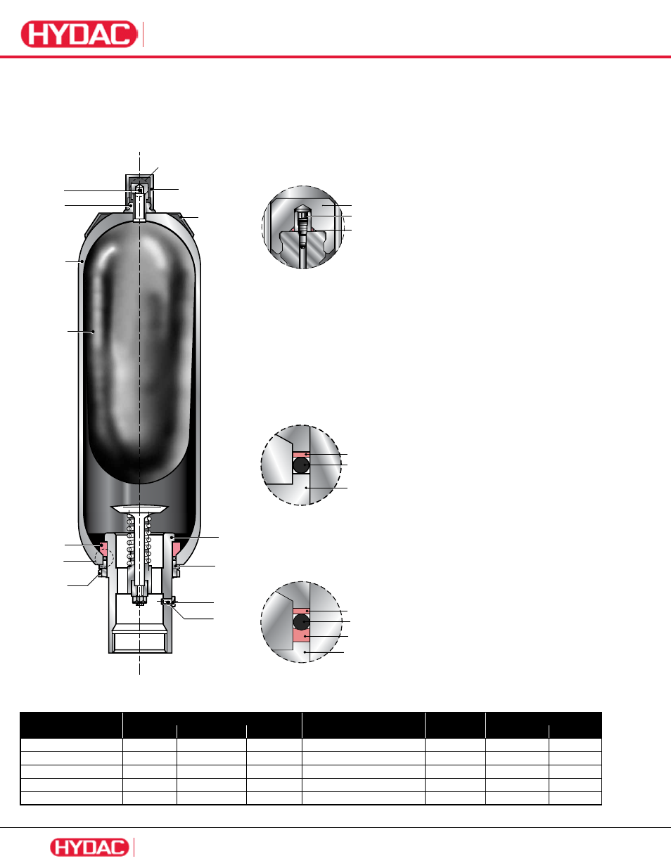
2. Replacement Parts Drawing:
SB210, SB330, SB330H, SB330N, SB400, SB500,
SB550 SB600, SB600N
Item Description:
1 Shell
2
Bladder
3
Gas Valve Core
4
Bladder Stem Lock Nut
5
Valve Seal Cap
6
Valve Protection Cap
7
O-ring
8
Name Plate
9
Fluid Port
14
Anti-extrusion Ring
15
Flat Ring
16
O-ring
17
Spacer Ring
18
Fluid Port Lock Nut
19
Fluid Port Vent Screw
20
Seal Ring
23
Back-up Ring
Repair Kit Consists Of:
2
Bladder
3
Gas Valve Core
4
Bladder Stem Lock Nut
(SB 600 only)
5
Valve Seal Cap
7 O-Ring
15
Flat Ring
16 O-Ring
23
Back-up Ring
(where applicable)
All SB 50L assemblies use the M50
(2”) diameter gas valve, not the M22 (7/8”) diameter
gas valve.
SB 600: size 10 to 54
SB 600N: size 10 to 54
SB330/400/500/550
(european mfg)10 to 50L