Multi-deck rotary switches – Grayhill Multi-Deck Rotary Switches 09 Series User Manual
Page 6
Grayhill, Inc. • 561 Hillgrove Avenue • LaGrange, Illinois 60525-5997 • USA • Phone: 708-354-1040 • Fax: 708-354-2820 • www.grayhill.com
Rotary Switches
Multi-Deck Rotary Switches
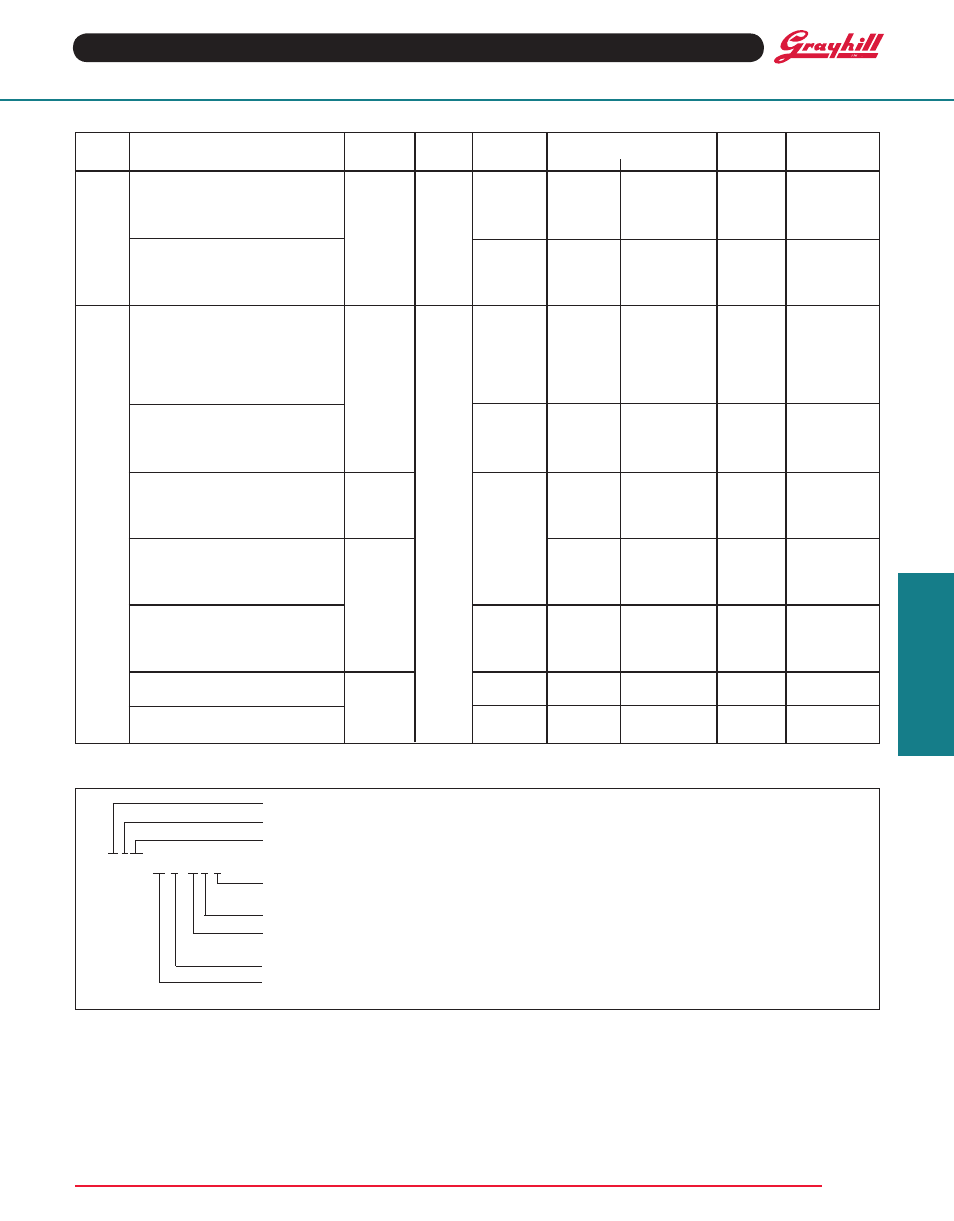
Angle
Number of Decks
Poles
Number of
Series
Style and Designation
of throw
Stops
terminals
Shorting
Non-Shorting Per Deck Positions/Pole
A = Standard
S = Standard, Shaft/Panel Seal
M = Military Style
MS = Style M, Shaft/Panel Seal
P = Standard, PC Mount
SP = Style P, Shaft/Panel Seal
MP = Military Style, PC Mount
MSP = Style MP, Shaft/Panel Seal
A = Standard
S = Standard, Shaft/Panel Seal
M = Military Style
MS = Style M, Shaft/Panel Seal
P = Standard, PC Mount
SP = Style P, Shaft/Panel Seal
MP = Military Style, PC Mount
MSP = Style MP, Shaft/Panel Seal
A = Standard,
S = Standard, Shaft/Panel Seal
M = Military Style
MS = Style M, Shaft/Panel Seal
A = Standard,
S = Standard, Shaft/Panel Seal
M = Military Style
MS = Style M, Shaft/Panel Seal
P = Standard, PC Mount
SP = Style P, Shaft/Panel Seal
MP = Military Style, PC Mount
MSP = Style MP, Shaft/Panel Seal
A = Standard
S = Standard, Shaft/Panel Seal
P = Standard, PC Mount
SP = Style, Shaft/Panel Seal
Solder
Printed
Circuit
Solder
Printed
Circuit
Solder
Printed
Circuit
Solder
Printed
Circuit
Fixed
Fixed
36°
30°
45°
60°
90°
08
09
CHOICES AND LIMItAtIONS
Series: determined by the angle of throw
Style*: Letter(s) from the Choices and Limitations chart
Angle of throw: Must agree with Series Number
09A30–03–1–12N–F
Stop Arrangement: Add letter C or F to a one pole per deck switch with the maximum number of positions
for a stop between position 1 and the last position.
type of Contacts: N = Non-shorting; S = Shorting
Positions Per Pole: Requires 02 positions as a minimum to the maximum allowable dependent on the
angle of throw and poles per deck
Poles Per Deck: As limited by angle of throw and switch style
Number of Decks: As limited by the angle of throw, the poles per deck, switch style and types of
contacts
* All rotary switches that are required to have military designated markings and testing adhering to MIL-3786 are to be ordered by specify-
ing the military part number identified on the appropriate slash sheet.
01 thru 12
01 thru 12
1
02 thru 10
01 thru 09
01 thru 09
2
02 thru 05
01 thru 12
01 thru 12
1
02 thru 10
01 thru 09
01 thru 09
2
02 thru 05
01 thru 12
01 thru 12
1
02 thru 12
01 thru 09
01 thru 09
2
02 thru 06
01 thu 06
01 thru 06
3
02 thru 04
01 thru 04
01 thru 04
4
02 or 03
01 thru 03
01 thru 03
5
02
01 thru 03
01 thru 03
6
02
01 thru 12
01 thru 12
1
02 thru 12
01 thru 09
01 thru 09
2
02 thru 06
01 thru 12
01 thru 12
1
02 thru 08
01 thru 06
01 thru 06
2
02 thru 04
01 thru 04
01 thru 04
3
02
01 thru 03
01 thru 03
4
02
01 thru 06
1
02 thru 006
01 thru 03
2
02 or 03
01 or 02
3
02
Not
01 thru 06
1
02 thru 06
Available
01 thru 03
2
02 or 03
Not
01 thru 06
1
02 thru 04
Available
01 thru 03
2
02
Not
01 thru 06
1
02 thru 04
Available
01 thru 03
2
02
ORDERING INFORMAtION
Not
Available