Multi-deck rotary switches, Shaft and panel seal, Circuit diagrams: pc mount – Grayhill Multi-Deck Rotary Switches 09 Series User Manual
Page 4: Pc board mounting pattern
Grayhill, Inc. • 561 Hillgrove Avenue • LaGrange, Illinois 60525-5997 • USA • Phone: 708-354-1040 • Fax: 708-354-2820 • www.grayhill.com
Rotary Switches
Multi-Deck Rotary Switches
SHAFt AND PANEL SEAL
A shaft and panel seal is available to provide watertight mounting of the Series 08
and 09. Standard and Military Style rotary switches. Sealing is accomplished by
O-ring shaft seal and panel seal washer. When the panel seal is compressed,
dimensions are approximately the same as an unsealed switch. Sealed switches
are provided with a double flat bushing. Non-turn feature can be accomplished by
proper fit of this bushing into panel hole and/or by allowing non-turn tab to extend
into (but not through) panel. Military Style rotary sealed switches do not have a
non-turn tab.
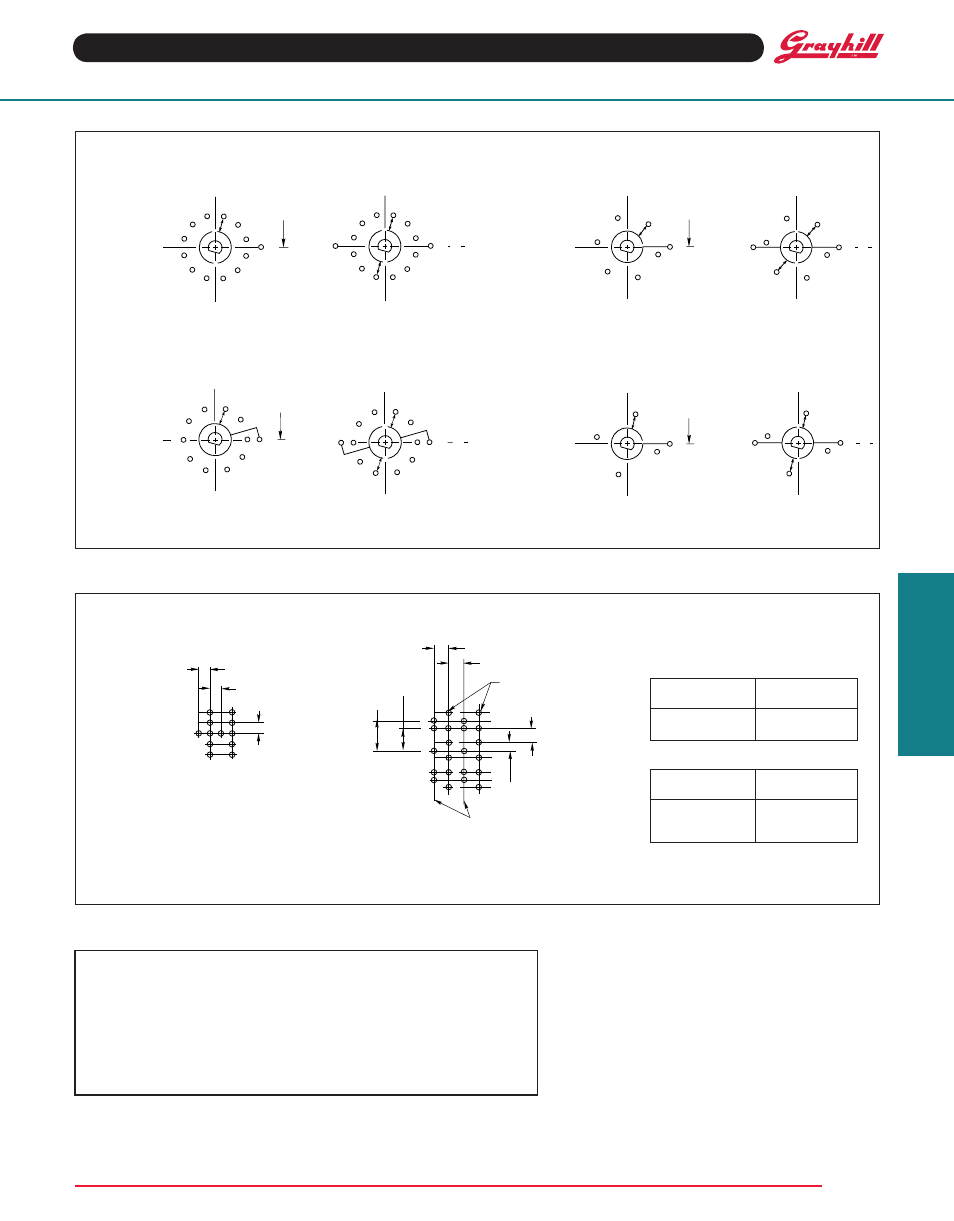
CIRCuIt DIAGRAMS: PC Mount
Switch is Viewed From Shaft End and Shown in Position No. 1
Note: All common terminals are located above base terminals as shown.
PC BOARD MOuNtING PAttERN
Series 09
30° Angle
of throw
ONE POLE
TWO POLE
ONE POLE
TWO POLE
Series 08
36° Angle
of throw
ONE POLE
TWO POLE
ONE POLE
TWO POLE
Number of Poles
Common terminal
Per Deck
Hole Location
1 Pole Per Deck
A
2 Poles Per Deck
A
30°, 60° and 90° Angle of throw
36° Angle of throw
Diagrams shown for a two deck switch. Bushing mounting is
recommended for all PC mount rotary switches.
Base terminals
Angle of throw
Hole Location
30°
All
60°
E and F
90°
D and F
Series 09
60° Angle
of throw
Series 09
90° Angle
of throw
C1
1
2
3
4
5
6
7
8
9
10
11
12
C
L OF
NON-TURN
TAB
C1
1
2
3
4
5
6
7
8
9
10
11
12
C2
C
L
7
6
5
4
3
2
1
8
9
10
C1
C
L OF
NON-TURN
TAB
7
6
5
4
3
2
1
8
9
10
C1 C
L
C2
C1
1
2
3
4
5
6
C
L OF
NON-TURN
TAB
C1
1
2
3
4
5
6
C
L
C2
C1
1
2
3
4
C
L OF
NON-TURN
TAB
C1
1
2
3
4
C
L
C2
.134 (3,40) TyP.
.134 (3,40) TyP.
.210
(5,33)
TyP.
.280
(7,11)
TyP.
SHAFT END
OF SWITCH
E
C
D
A
C
B
F
E
D
.070
(1,78)
.140
(3,56)
TyP.
COMMON TERMINAL ROW
HOLE LOCATION (SEE CHART)
BASE TERMINAL
ROW HOLE LOCATION
(SEE CHART)
.134 (3,40) TyP.
.134 (3,40) TyP.
.140
(3,56)
TyP.
SHAFT END
OF SWITCH