Gast 2567 Series Oilless Vacuum Pumps and Compressors User Manual
Page 6
10. Release shaft and rotate rotor to next position.
Check rotor lobe. Set each clearance to the
tightest setting. Repeat until all lobes have been
checked.
11. Remove from fixture and tighten remaining screws.
12. Either leave dowel pins out or drill new dowel pin
holes and use new dowel pins.
Do Not re-use old
dowel pins.
Check that all external accessories such as relief valves
and gauges are attached to cover and are not
damaged before re-operating product.
If pump still does not produce proper vacuum or
pressure, send unit to a Gast Authorized Service
Facility for repair.
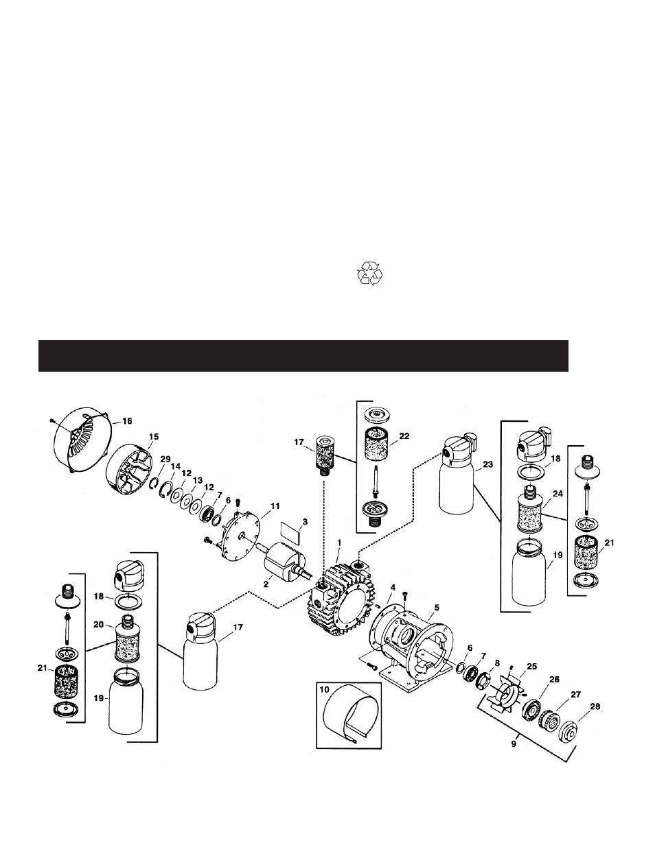
EXPLODED PRODUCT VIEW, PARTS & ORDERING INFORMATION
6
For the following exploded view, please reference Series and Model parts chart on facing page.
Disposal
(Please note current regulations)
Parts of the rotary vane pumps and
compressors, shafts, iron or aluminum castings,
plastic or glass parts or bearings, may be
recycled as scrap materials.
Replacing New Body or Rotor
1.
Use a micrometer to read the rotor length and
body thickness. Subtract rotor length from body
thickness. Check with Factory for clearances.
2.
For desired rotation, the inlet port needs to be to
the left of the body for counter-clockwise rotation
or to the right for clockwise rotation.
3.
If gasket is needed, place one or more gaskets on
body face.
4.
Place rotor through body bore.
5.
Place drive end plate on body gasket.
6.
Install all screws and hand tighten.
7.
Place motor with drive down in fixture and apply
pressure to hold against drive end plate.
8.
Place a .003” shim between rotor and body bore.
Tap body toward or away from rotor until shim is
snug and resists being moved.
9.
Tighten bolts at the 9:00 and 3:00 o’clock positions.