Valve repair - disassembly, Float bonnet assembly, Replacing spool seals – Bush Hog 765H User Manual
Page 21: Figure 11
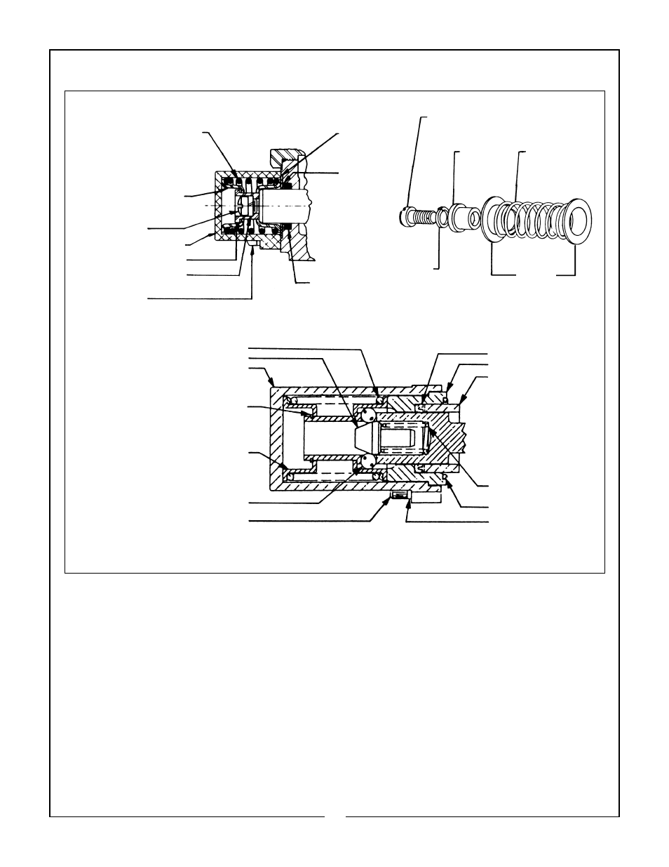
VALVE REPAIR - DISASSEMBLY
RETAINER
BACK-UP
WASHER
SCREW 5/16-18 x 3/4
SPOOL
COLLAR
RETURN
SPRING
SPRING
COLLAR
LOCKWASHER
O-RING SEAL
RETURN SPRING
SPRING COLLAR
SCREW, 5/16-18
x 3/4
SPOOL COLLAR
LOCKWASHER
SCREW, 1/4-20
x 7/8
RETURN SPRING
DETENT BALL FOLLOWER
BONNET
RETAINING RING
STOP COLLAR
DETENT BALL
SCREW, 1/4-20 x 7/8
U-CUP SEAL
FLOAT SLEEVE
RETAINING SLEEVE
DETENT SPRING
O-RING SEAL
LOCKWASHER
FLOAT BONNET ASSEMBLY
STANDARD SPRING CENTERED BONNET ASSEMBLY
Replace Center Section Assemblies:
Note: For the purpose of these instructions we will consider
the section containing the MAIN RELIEF VALVE as the left
side of the valve.
1. Remove control valve from the backhoe.
2. Thoroughly clean the exterior of the valve before
beginning disassembly procedures.
3. Since the valve will be assembled in the same
order, each section should be marked numerically so
that they can be reassembled in the same sequence.
4. Mount the valve vertically in a vise to facilitate dis-
assembly and assembly.
5. Remove the 3 tie rod nuts from the right end sec-
tion, using a thin-wall socket.
6. Valve sections can now be removed by sliding the
sections along the tie rods.
7. Thoroughly clean the O-ring counterbores and the
ground surfaces of each section. Place O-ring seals,
ordered as a kit, in proper counterbores. For better
sealing it is recommended that all O-rings, used in the
counterbores, are replaced with new parts.
8. Replace the sections on tie rods with the O-ring
counterbores facing the right end of the valve. Be
careful replacing the sections so that the section O-
rings are not moved from the counterbores.
9. When all sections are assembled on the tie rods,
tighten the tie rod nuts equally to 20 ft. lbs. torque, NO
MORE - NO LESS, or spools may bind and stick.
Replacing Spool Seals:
Note: For the purpose of these instructions we will consider
the control handle side of the valve as the FRONT, and the
opposite side as the BACK.
19
Figure 11