Flint & Walling Multi-Stage Effluent 4 (10 cm) Submersible Pump User Manual
Page 5
© Copyright 2007. All Rights reserved.
5
SK2222
Major Components
1. Submersible Effl uent Turbine Pump - A submersible ef fl u ent
tur bine pump is a multistage centrifugal design pump. Each stage
con sists of an impeller and diffuser. Water pres sure in creas es in
equal amounts as it passes from stage to stage. The more stag es,
the higher the pressure the pump will de vel op.
To correctly select a pump for a specifi c application, the fol low ing
information must be known:
• The amount of discharge required in GPM or LPM
• The total dynamic head required in feet or meters
Use this information along with the performance data found on the
previous page to make your selection.
2. Control Panel - Submersible effl uent turbine pumps re quire the
use of an above ground control panel or junction box with a pump
control switch for proper op er a tion. Op er a tion of these pumps
without a control pan el or junction box with a pump control switch
can result in failure of the pump and void the war ran ty.
3. Float Switches - All submersible effl uent turbine pumps are non-
au to mat ic. The use of fl oat switches are required for the proper
operation of the pump. Operation of these pumps without fl oat
switch es can result in failure of the pump and void the warranty.
A minimum of two fl oat switches should be used in each ap pli -
ca tion:
• A pump control fl oat switch
• A high water alarm fl oat switch
4. Piping - The submersible effl uent turbine pump can be in stalled
with schedule 40 PVC pipe. The pipe size should be 1¼” diameter
for the 10 GPM to 27 GPM pump series and 2” diameter for the 35
GPM pump series.
General piping from the pump to a splitter, distribution box, drain
fi eld etc., should be the same diameter as stat ed above. For long
pipe runs consult friction loss tables for correct pipe sizing.
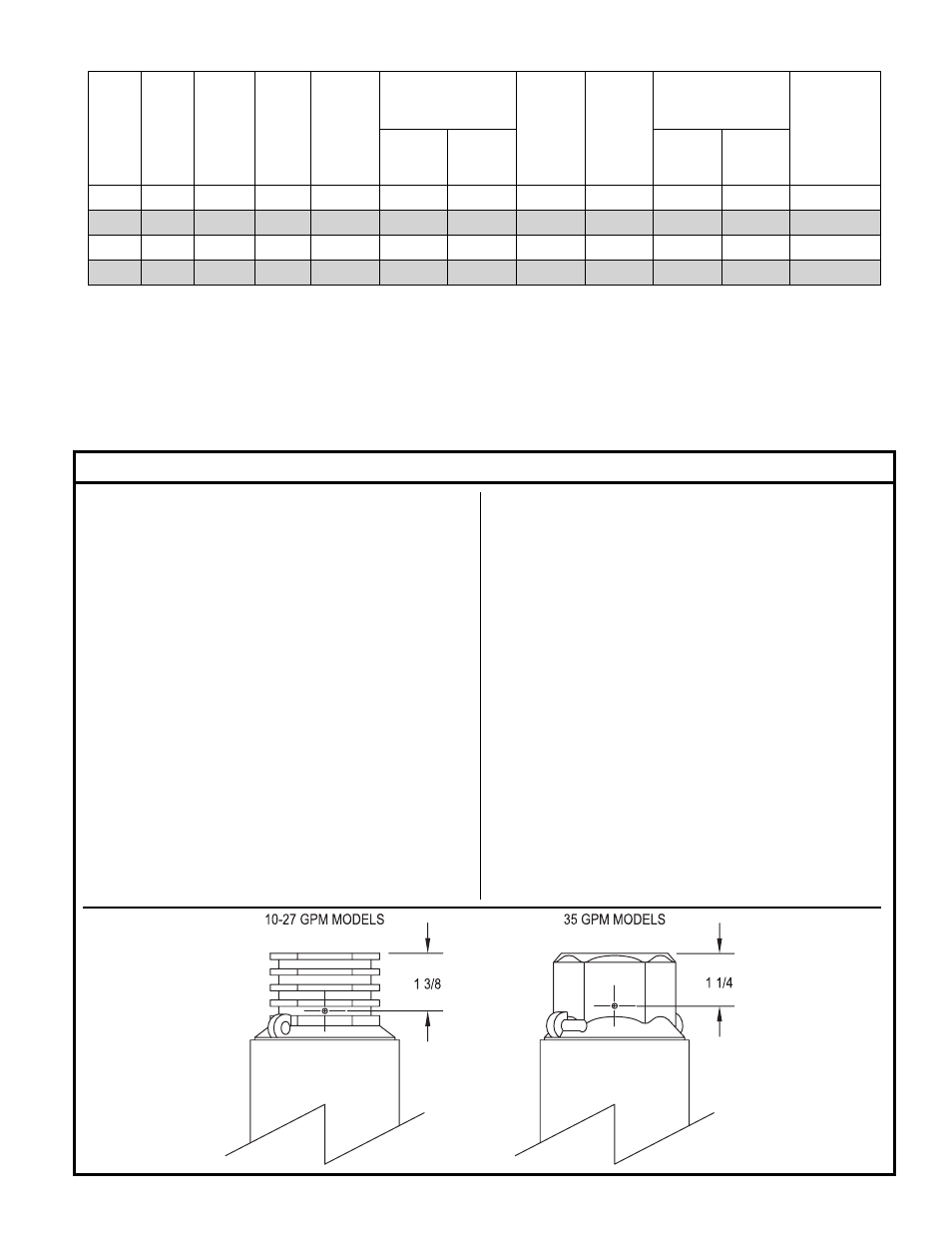
5. Check Valve - A check valve is required in all duplex sys tems. It is
also required when a large amount of effl uent can backfl ush into the
system causing rapid cycling of the pump.
A 1/8” weep hole must be drilled in the side of the discharge
head when using a check valve (see drawing below for drill
location).
Electrical Data for Flint & Walling Effl uent Turbine Pumps
HP
Volts Phase
Hz
S.F.
Maximum
Locked
Rotor
Amps
KVA
Code
Fuse/Circuit
Breaker Amps
Winding
Resistant
Line to
Line
Amps
Watts
Std.
Delay
1/2
115
1
60
1.6
12
970
64.4
R
30
15
1.0 - 1.3
1/2
230
1
60
1.6
6
970
32.2
R
15
8
4.2 - 5.2
3/4
230
1
60
1.5
8
1325
40.7
N
20
10
3.0 - 3.6
1
230
1
60
1.4
9.8
1600
48.7
N
25
11
2.2 - 2.7