115 volt installation – Flint & Walling Booster Pump Flow Protector Instructions User Manual
Page 3
3
FLINT & WALLING, INC. • 95 North Oak St. • Kendallville, IN 46755 • www.flintandwalling.com
WIRING PROCEDURES FOR 115V CONTROL
Make certain that the power supply
conforms to the electrical specifications of the motor
supplied. If the motor wiring must be changed to conform to
your specific voltage requirements, consult documentation
provided with the pump motor for correct procedure.
1. Install and maintain your pump in accordance with your
local electrical code and all other codes and ordinances
that apply. Consult your local building inspector for local
code information.
2. Plug the 115V power cord from the electronic flow
protector box into a properly grounded 115V receptacle.
3. Plug a properly sized and grounded power cord from the
pump motor into the “piggy back” outlet of the power
cord of the electronic flow protector.
IMPORTANT: Check local and/or United States National
Electric Codes for proper grounding information.
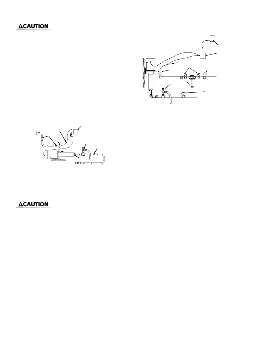
HOSE
ADAPTER
HIGH PRESSURE
REINFORCED HOSE
HIGH PRESSURE
REINFORCED HOSE
WALL HYDRANT
INLET
PRESSURE RELIEF
VALVE
HOSE ADAPTER
OUTLET
SPRAY
NOZZLE
CONNECTORS
ELECTRONIC FLOW PROTECTOR
FLOW
SENSOR
TO DRAIN
IL0630
F&W
115 VOLT INSTALLATION
115 VOLT
Figure 3
WIRING PROCEDURES FOR 230V CONTROL
Make certain that the power supply
conforms to the electrical specifications of the motor
supplied. If the motor wiring must be changed to conform to
your specific voltage requirements, consult documentation
provided with the pump motor for correct procedure.
1. Feed the lead wire labeled Output (Motor) from the
electronic flow protector to the terminal block of the
motor.
2. Connect the green ground wire first to the grounding
terminal provided on the motor frame. Ground connection
MUST be made to this terminal. Do not connect motor to
electrical power supply until unit is permanently grounded;
otherwise serious or fatal electric shock hazard may be
caused.
3. Attach the black and white wires to the power
supply terminals or wires of the pump motor, consult
documentation provided with the pump motor for correct
location and wiring procedures.
4. Feed the lead wire labeled Input Power from the electronic
flow protector to your 230V electrical power supply.
5. Connect the green ground wire first to the grounding
terminal within the electrical supply box as specified by
local or United States National Electrical code. Do not
ground to a gas supply line. Do not connect the electronic
flow protector to electrical power supply until unit is
permanently grounded; otherwise serious or fatal electric
shock hazard may be caused.
6. Connected black and white wires as specified by local or
United States National Electrical code to the disconnected
supply voltage.
PRESSURE GAUGE
FUSE DISCONNECT OR BREAKER BOX
ELECTRONIC FLOW PROTECTOR
GATE/BALL VALVE
FROM
WATER SOURCE
GATE/BALL VALVE
(NORMALLY OPEN)
TO DRAIN
LINE FILTER
PRESSURE
RELIEF VALVE
CONNECTORS
FLOW SENSOR
F&W
230 VOLT
230 VOLT INSTALLATION
IL0628
Figure 4
OPERATION:
Priming of the pump is automatic when pump is connected to
a positive supply of water such as a hydrant or city main.
1. Disconnect power to the electronic flow protector and
pump. (Unplug 115V model, turn off disconnect to 230V
model.)
2. Open values and/or nozzle on suction and discharge side of
the pump.
3. To relieve trapped air, allow water supply to run a
minimum of 30 seconds before starting the pump.
4. Connect power to the electronic flow protector and pump.
(Plug in the 115V model, turn on disconnect to 230V
model.)
5. As long as there is at least 1.0 GPM of water flowing
through the pump, the pump will continue to run. If the
water supply or discharge valve and/or nozzle is closed,
which causes less that 1.0 GPM of water to flow through
the pump, the electronic flow protector will turn off the
pump in 20 to 30 seconds. Once the flow has returned to
at least 1.0 GPM, the flow protector will turn the pump
back on.