Dimensions in inches – Flint & Walling C22000 User Manual
Page 2
2
95 North Oak Street • Kendallville, IN 46755
Copyright 2012. All Rights Reserved.
SUCTION LIMITATIONS
1. Units are non self-priming. Normally after being
primed the total suction lift of the pump is 15 feet.
2. Where liquids at or near their boiling points are
being handled, the supply must be located above
the suction, so that the available NPSH will be
greater than that required by the unit.
PIPING
1. Do not use the pump as support to the piping. The
pipe must be independently supported near the
pump so that no strains will be transmitted to the
unit. Failure to do so will cause premature pump
failure and will void the warranty.
2. Suction and discharge sizes are selected for proper
performance of the pumping unit and are not
intended to determine the suction and discharge
pipe sizes. Pipe sizes must be determined by the
user based on the system requirements.
3. Install both a union and a gate valve (not furnished)
on the suction and discharge side of the pump for
service convenience.
CAUTION: Do not use a globe or other restricting
type of valve at the discharge. Globe valves seriously
restrict the capacity of the pump.
4.
All joints and connections should have pipe sealing
compound (male threads only) applied and drawn
up tightly.
CAUTION: The entire system must be air and water
tight for efficient operation.
SUCTION PIPING
1. Suction piping should be short in length, as direct
as possible, and never smaller in diameter than the
pump suction opening.
2. Use galvanized piping, rigid plastic or other suitable
pipe that will not collapse under suction.
3. The suction pipe should slope upward to the pump
inlet. A horizontal suction line must have a gradual
rise to the pump. Any high point in the pipe will
become filled with air and thus prevent proper
operation of the pump. When reducing the piping
to the suction opening diameter use an eccentric
reducer with the eccentric side down to avoid air
pockets. Never use a straight taper reducer in a
horizontal suction line, as it tends to form an air
pocket in the top of the reducer and the pipe.
Valves in Suction Piping
1. If the pump is operating under static suction lift
conditions, a foot valve may be installed in the
suction line to avoid the necessity of priming each
time the pump is started.
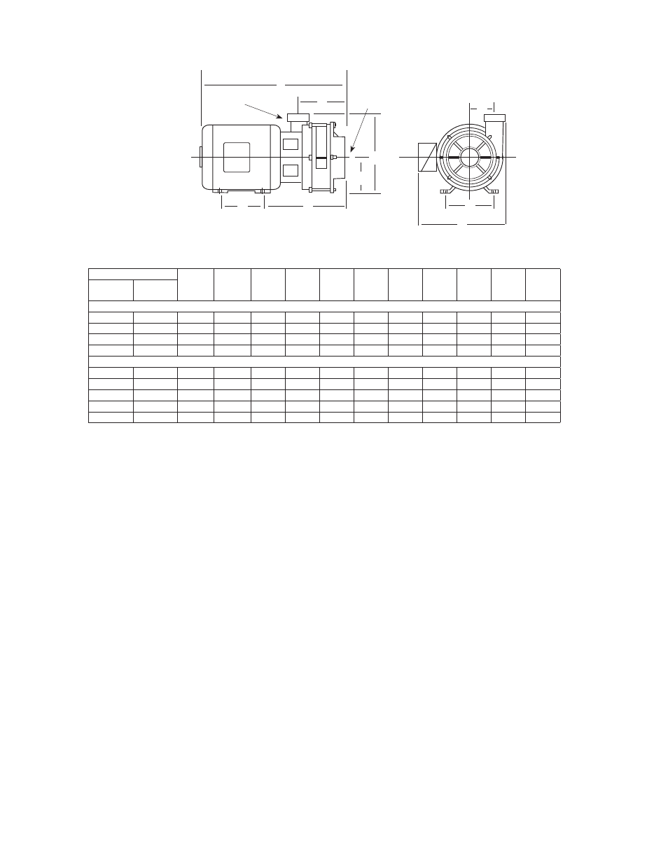
DIMENSIONS in INCHES
Figure 1
C22000 SERIES
Catalog Number
HP
Motor
Frame
Size
A
B
C
D
E
F
G
J
K
1 Phase 3 Phase
SINGLE STAGE 3500 RPM
C22131
—
3
182JM
4.50
7.50
10.24
4.50
10.81
4.06
12.12
19.49
3.44
—
C22133
3
145JM
5.00
5.50
9.49
3.50
9.81
4.06
10.50
17.87
3.44
C22151
—
5
184JM
5.50
7.50
10.24
4.50
10.81
4.06
12.12
20.49
3.44
—
C22153
5
182JM
4.50
7.50
10.24
4.50
10.81
4.06
12.12
20.49
3.44
TWO STAGE 3500 RPM
C22231
—
3
182JM
4.50
7.50
12.49
4.50
10.81
6.31
12.12
20.49
3.44
—
C22233
3
145JM
5.00
5.50
11.74
3.50
9.81
6.31
10.50
20.12
3.44
C22251
—
5
184JM
5.50
7.50
12.49
4.50
10.81
6.31
12.12
22.74
3.44
—
C22253
5
182JM
4.50
7.50
12.49
4.50
10.81
6.31
12.12
22.74
3.44
—
C22273
7-1/2
184JM
5.50
7.50
12.49
4.50
10.81
6.31
12.12
22.74
3.44
Dimensions shown above are approximate maximum dimensions for standard pumps equipped with open drip
proof motors.
J
IL1000
A
C
D
E
F
2” Discharge
3” Suction
K
B
G