Bunn VLPF User Manual
Page 21
Page 21
SERVICE (cont.)
LIQUID LEVEL CONTROL SYSTEM (cont.)
Removal and Replacement:
1. Remove all wires from the liquid level control
board terminals.
2. Remove the two #8-32 slotted-head screws hold-
ing the circuit board to the brewer hood.
3. Install the new circuit board to the hood, making
sure that the two lock-washers are in place below
the board and above the spacers.
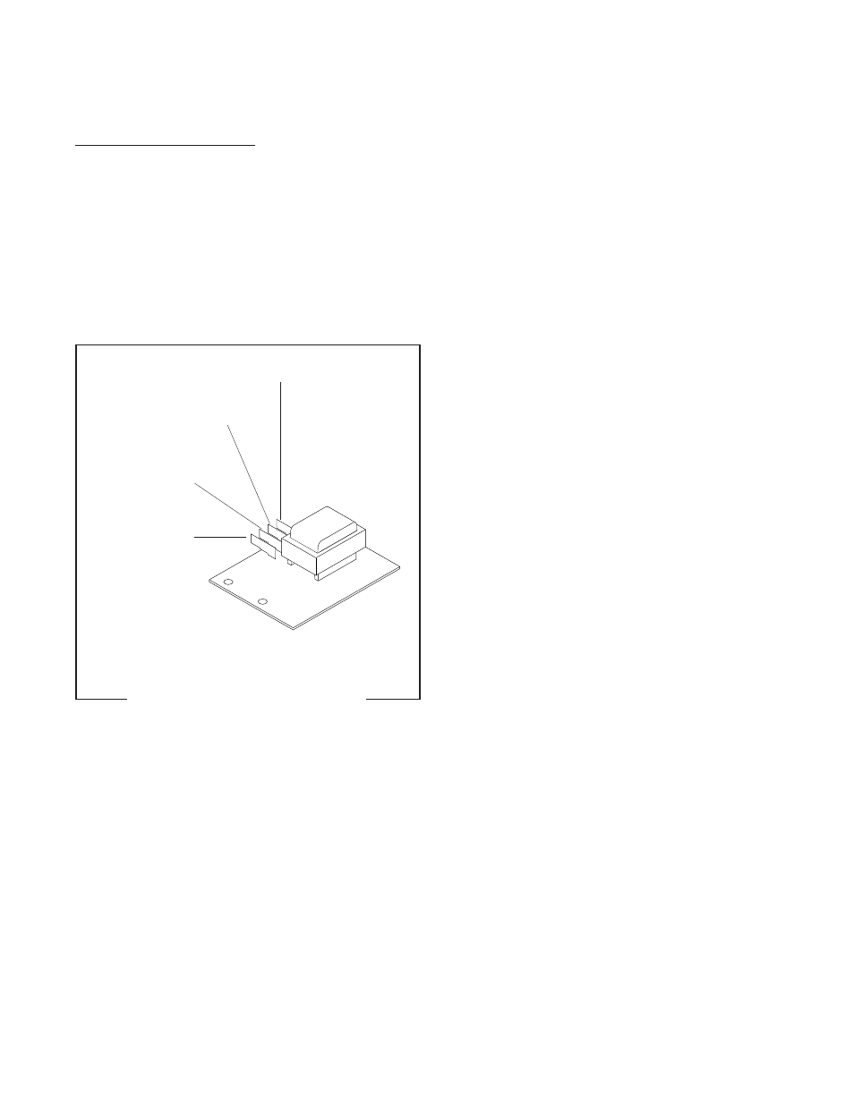
4. Refer to FIG. 13 when reconnecting the wires.
WHI/BRN to Relay (Term. #2)
WHI/RED to Start Switch
WHI/RED to Relay(Term. #5)
WHI to Timer
WHI to Solenoid
PNK to Probe
FIG. 13 LIQUID LEVEL CONTROL
BOARD TERMINALS
P1985.70
10179 060100
See also other documents in the category Bunn Coffee machines:
- A-10 (12 pages)
- CEZ-TS (32 pages)
- CDBC-DV (37 pages)
- CWT APS (2 pages)
- CWT-TSR (33 pages)
- CWT-TS (24 pages)
- CRT5 CRTF5 (32 pages)
- CWTF-TSR-MV (31 pages)
- Dual Voltage Models Starting at Serial #CDBC024477 CDBCF TC (32 pages)
- CRT5 (32 pages)
- XL M-2 (2 pages)
- CDBCF15-TC (2 pages)
- C (59 pages)
- C (32 pages)
- ESPRESS ES2C (17 pages)
- VPR (17 pages)
- CRT5 (7 pages)
- WL2 (2 pages)
- A10 Automatic (6 pages)
- 120/208V (2 pages)
- EASY POUR WX1 (2 pages)
- ES2SA (35 pages)
- BT10 (3 pages)
- TU3Q-EZ (22 pages)
- TWIN APS (32 pages)
- DUAL GPR-DBC WITH SMART FUNNEL 41343 (38 pages)
- VP17A (24 pages)
- VP17A (8 pages)
- AXIOM BREWWISE 39131.0004B (19 pages)
- CEZF CDBC (36 pages)
- BX-B (16 pages)
- ESPRESS ES.1AF (12 pages)
- 37614 041410 (7 pages)
- CWTF TWIN (35 pages)
- VPR TC (12 pages)
- Titan Single Brewer (2 pages)
- AutoPOD Brewer 41167.0001B (13 pages)
- Coffee Warmer (3 pages)
- CWTF-TC (1 page)
- VPR VPS (5 pages)
- BTC (12 pages)
- Tiger Super Automatic Espresso Machine with Steam Wand XL S-2 (2 pages)
- CWT APS-DV (31 pages)
- Dual TF DBC (56 pages)