Emergency stop safety relay esm-bl2, User information – EUCHNER ESM-BL2xx User Manual
Page 2
2
User Information
EUCHNER GmbH + Co. KG Kohlhammerstraße 16 D-70771 Leinfelden-Echterdingen Tel. +49/711/75 97-0 Fax +49/711/75 33 16 www.euchner.de [email protected]
Emergency Stop Safety Relay ESM-BL2..
Note: The items listed under “Electrical connection” must be observed during commissioning.
Commissioning
Procedure
1. Wiring emergency stop circuit:
Wire the emergency stop circuit according to the required
Performance Level determined (see Fig. 1 to Fig. 3).
2. Wiring start circuit:
Wire the start circuit according to Fig. 4 or Fig. 5 to set the
starting behavior.
Warning:
If “Automatic start” is set, bear in mind that the safety con-
tacts will switch immediately after the power supply is
connected. If “Manual start” is set, the start button must be
opened after wiring.
3. Wiring feedback loop:
If your application provides for external contactors or ex-
pansion modules, connect them to the device according to
Fig.6 or Fig.7.
4. Wiring power supply:
Connect the power supply to terminals A1 and A2.
Warning: Wiring only in de-energized state.
5. Starting the device:
Switch the operating voltage on.
Warning:
If the “Automatic start” starting behavior is set, the safety
contacts will close immediately.
If the “Manual start” starting behavior is set, close the start
button to close the safety contacts.
LEDs K1 and K2 are lit.
6. Triggering safety function:
Open the emergency stop circuit by actuating the con-
nected safety switch. The safety contacts open immedi-
ately.
7. Reactivation:
Close the emergency stop circuit. If “Automatic start” is
selected, the safety contacts will close immediately.
If the “Monitored manual start” starting behavior is set, close
the start button to close the safety contacts.
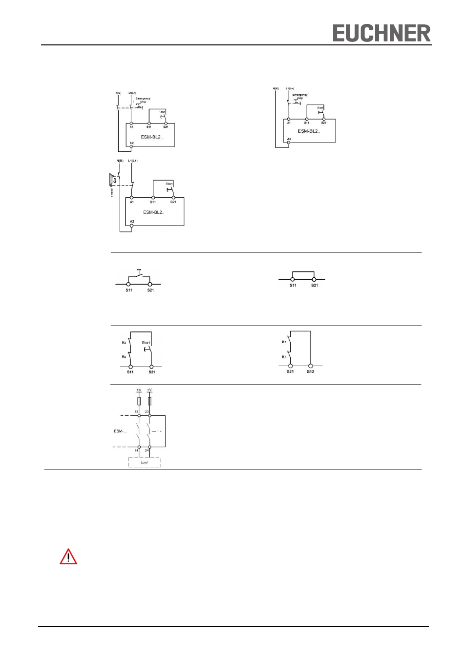
Fig. 4:
Manual start.
Fig. 5:
Automatic start
(e.g. for applications with a
safety door).
Warning:
Safety contacts switch
immediately when the
power supply is connected.
Depending on the application or the result of the risk assessment according to EN ISO 13849-1, the device must be wired as
shown in Fig. 1 to Fig. 9.
Applications
Fig. 1:
Two-channel emergency stop
circuit without fault monitoring of
the emergency stop button and
the supply cables.
(up to category 3, PL d)
Fig. 2:
Single-channel emergency stop
circuit without fault monitoring of
the emergency stop button and
the supply cables.
(up to category 1, PL c)
Emergency Stop
Circuit
Starting Behavior
Fig. 3:
Two-channel sliding guard monitoring
with positively driven limit switches.
(up to category 3, PL d)
Fig. 6:
Feedback loop for monitored manual
start:
The feedback loop monitors contactors
or the expansion modules .
Feedback Loop
Fig. 7:
Feedback loop for automatic start:
The feedback loop monitors contac-
tors or the expansion modules .
Safety contacts
Fig. 8:
Connecting load to safety contacts.
(Figure shows example.
Voltage „+V“ according to techn.
data)
Notice:
In order to activate earth fault monitoring, S10 must be con-
nected to PE (protective earth) on the AC115/230V devices.
With AC/DC 24 V, connect PE only to the power supply unit
according to EN60204-1.